107 | Analysing Turbo Performance
Summary
Turbocharging is a common way of increasing engine power, but many tuners have little understanding of how to analyse the performance of their turbocharger, how to read a compressor map, and how to confirm the turbo is suitable for a particular application. In this webinar we will look at how to analyse turbo performance using parameters such as exhaust pressure, turbo speed and mass airflow.
| 00:00 | - It's Andre from the High Performance Academy. |
| 00:02 | Welcome to this webinar where we're going to be looking at how we can analyse the performance of a turbocharger system. |
| 00:09 | Now, turbochargers are nothing new. |
| 00:11 | We've been relying on them in the aftermarket particularly to provide insane levels of engine performance and power for a long time. |
| 00:20 | There is a lot of technology involved with a turbocharger design and development. |
| 00:25 | They've also come a long way over the last decade or more, and what this had done for us in the aftermarket is provide a better response, more power for the same amount of boost and generally a more reliable turbocharger product. |
| 00:40 | At the same time, because turbochargers are a relatively complex device, there's a lot behind the operation of the turbocharger. |
| 00:49 | I find that a lot of tuners don't have a really good understanding of the factors behind turbo selection and optimising a turbocharger for a certain engine application. |
| 01:00 | So what we generally see in the aftermarket is a lot of trial and error, and to some degree this can be essential. |
| 01:09 | What we tend to see is basically shops or clients will develop a certain turbocharger package to suit a specific engine that they work with frequently that they know is gonna deliver a certain level of performance that they're happy with, and I've fallen into exactly that same category with my old workshop. |
| 01:30 | We were doing a lot of development on the Mitsubishi Lancer Evo and one of our favourite packages or most common with the packages was to fit the Garrettt GT with GTX 3582 turbocharger in various trims, and we found that that was a good way of making somewhere in the range of about 300 kilowatts at the wheels on our old Dynapack dyno on pump gas. |
| 01:56 | Now that turbocharger is probably starting to show its age and there's certainly some better options out there on the market. |
| 02:04 | It comes down to how do we decide whether the turbocharger we have selected is doing the job as well as it could, and in this webinar, I'm going to hope to explain some of the principles behind this, as well as how we can use data analysis on the car in order to decide whether the turbocharger is doing what we want, whether our turbocharger is selected correctly, whether it's too big or too small for the application. |
| 02:34 | The parts briefly that I'm going to cover inside this webinar, we're going to start by looking at the compressor map. |
| 02:42 | We're going to look at each of the components of a compressor map and understand what they mean, how they relate to the performance of the turbocharger, and we're going to look at how to read a compressor map. |
| 02:55 | We're also going to look at how to choose a compressor to suit a compressor map, to suit our desired aims so that we know that we're selecting something that's going to suit both our horsepower aims as well as our engine capacity, our engine size. |
| 03:11 | We're going to discuss what A/R is as it relates to both the turbine housing and the compressor housing. |
| 03:19 | Then finally we're going to move into analysing the performance of your turbocharger and that's going to involve some running over our Toyota 86 here on our Mainline Dyno. |
| 03:29 | Now, for those who aren't aware, our Toyota 86 is fitted with a BorgWarner EFR 6758 turbocharger. |
| 03:38 | We're going to look, because this is a very well instrumented engine, we've got a lot of data coming into our MoTec M150 ECU so we can see exactly how that turbocharger is performing and it's going to allow us to see both in steady state and under a ramp run condition exactly where we are running on that compressor map. |
| 03:59 | We're also going to be analysing the performance of the exhaust side of the turbocharger too and see how our exhaust pressure relates to our turbocharger's performance. |
| 04:11 | As usual, if you do have any questions during the course of the webinar, please put those into the chat box and Colin is going to transfer those through to me and I'll do my best to answer your questions at the end of our webinar. |
| 04:26 | What we're going to do is we're going to start by looking at our compressor map. |
| 04:31 | In order to do this, let's jump to the my laptop screen. |
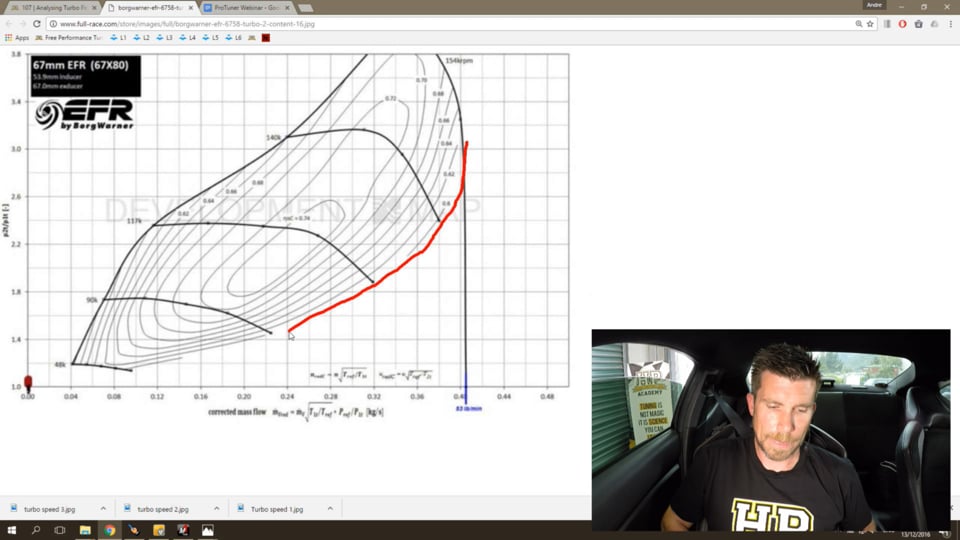
| 04:36 | We've got a compressor map here which is for our 6758 BorgWarner. |
| 04:43 | This is the compressor that is currently fitted to our Toyota 86. |
| 04:48 | This is going to be relevant because a little later when we're actually running the car, I'm going to be plotting some of the data on to this compressor map. |
| 04:57 | So what we want to do is focus on the individual components of our compressor map. |
| 05:03 | And I'm gonna talk about this individually. |
| 05:06 | So first of all, let's take a look at the axis that we have on the bottom. |
| 05:10 | And you can see that its label here as corrected mass flow. |
| 05:15 | Now what this is is mass air flow. |
| 05:18 | This is the mass of air that the compressor is able to move and this is key to some of our selection criteria because in order to make a certain amount of horsepower from our engine, we need the compressor to be able to deliver X amount of air flow. |
| 05:38 | Now the key point here is we are talking about mass air flow, not volume flow, so the difference there, when we're talking about volume flow, you might hear numbers that are related in cubic feet of air per minute, what we're interested in, is the mass of air, because it's the mass of oxygen the mass of air that we're interested in, that's what we need in order for our engine to make power. |
| 06:02 | So in order to calculate our mass flow, we need to take our volume flow, and also consider air density in that equation. |
| 06:12 | Now on this particular graph here, our x axis value are actually in a metric term, they're in kilogrammes of air flow, mass air flow per second, it's more common to represent, in my experience, represent mass air flow with turbo compressor maps, in pounds per minute, that's generally what we'll see on most compressor maps. |
| 06:39 | So unfortunately, BorgWarner here throws us a little bit of a curve ball by using the metric scale system here. |
| 06:45 | Now what you can see is, there is a line here, that comes down and sits right here, and it's says 53 pounds per minute, and basically, for this particular compressor, this is the maximum amount of air flow that the compressor can deliver, 53 pounds of air per minute, which works out to be a touch over 0.4 kilogrammes per second. |
| 07:12 | Okay, so what we need to understand here is, that while there is a little bit of variance in round terms, we need somewhere between about 9.5 and 10.5 pounds of air per minute, in order to make 100 horsepower. |
| 07:28 | So in round numbers here, this compressor map's showing that it's able to support 53 pounds per minute of mass air flow, this suggests that this turbo charger, really stretched to it's limits, could potentially support somewhere in the region of about 500 horsepower. |
| 07:44 | This is one of our key criteria, looking at the right hand side of our compressor map here, and tracing this line back down through the mass flow axis, this will show us the maximum amount of air flow, and hence the maximum air flow, I'm sorry, power potential, of a given compressor wheel. |
| 08:07 | Okay, now we can move on, and we're going to look at our other axis, so the vertical axis in this case, is the pressure ratio. |
| 08:16 | And I find this is an axis that's a little bit misunderstood, in simple terms, it's really easy to understand, it is the outlet pressure from the compressor, or the turbo charger, divided by the inlet pressure. |
| 08:31 | So most people would just take into account that the inlet pressure would be our atmospheric pressure, and take that as a 101.3 kPa standard pressure at sea level, and be done with it. |
| 08:44 | So in other words, and round numbers, if we were running 200 kPa of positive boost pressure, 200 kPa of boost pressure, I should say, absolute, and we had our atmospheric pressure, let's say, 100 kPa, this would simply be, 200 divided by 100, it would give us a pressure ratio of 2:1. |
| 09:05 | However, we do need to consider what the inlet pressure is, and how that works. |
| 09:11 | So one of the simplest things to overlook is how our pressure ratio changes as altitude changes, so let's say, for example, we have 200 kPa of boost pressure, we have 100 kPa of inlet pressure, and our pressure ratio is 2:1, so, in this case, on our table here on our compressor map, we're operating through this line on our pressure ratio axis. |
| 09:37 | Now, let's say we drive the car up to high altitude, and our barometric air pressure at ambient air pressure, drops down to zero, or to 85 kPa, wouldn't be outside of the realms of possibility, let's pull up a calculator and see now how that works. |
| 09:55 | And if we just clear that, so we have 200 kPa still, our compressor, our turbo boost control system, has maintained an inlet manifold pressure of 200 kPa, despite the fact that we've climbed up in altitude. |
| 10:11 | But now we're dividing this by 85 kPa, and this gives us a pressure ratio of 2.35, so now, we're, instead of operating at a pressure ratio of 2:1, we're somewhere up around here. |
| 10:25 | So you can see that the inlet pressure, and particularly, this is a consideration with altitude, has a dramatic effect on exactly whereabouts we're operating inside the compressor map. |
| 10:37 | And if we want to maintain that same inlet manifold pressure, absolute manifold pressure, as our altitude changes, and our barometric air pressure changes, what this essentially means is, as we climb higher in altitude and the baro pressure drops, we're driving the turbo charger harder and harder, in order to maintain that same inlet manifold pressure. |
| 11:02 | The other thing that can also affect our pressure ratio, though, that we need to take into account, is if our inlet system is restrictive, and this is quite common in the case of a factory turbo charged engine, it's quite possible that we're going to end up with a lower pressure at the compressor inlet, than what we actually have in our barometric air pressure, or our ambient air pressure, so that's another consideration we do need to take into account. |
| 11:31 | Obviously, on a competition vehicle, with a well designed inlet system, a free flowing air box, free flowing air filter, this should be less of a consideration, but it is still something that is very easy to overlook. |
| 11:46 | Okay, so we now understand what the two axis on our compressor map mean, now there's a few more things to consider though, first of all, we can see that inside the compressor map here, we have what's known, what's labelled as efficiency island so, I'm doing a really bad job of drawing around those, but you kind of get the idea, these are the efficiency islands that we're talking about, and you can see that they're also labelled, so in the case of our peak efficiency island here, we're setting at 74% with 0.74, and as we move out through the islands towards the right, where we're driving the compressor harder, moving outside of its efficiency, we drop to 0.6, or 60% efficiency. |
| 12:32 | Okay, so what's this efficiency actually mean, what's its relevance? So what we need to understand is as we compress air, it naturally will be heated up, that's just a fact that we have to deal with as we compress air it will be heated up. |
| 12:51 | Now if our compressor is 100% efficient, which obviously, is not possible, but if it was 100% efficient, then we could calculate the temperature gain, between the inlet temperature and the outlet temperature, by using the Ideal Gas Law. |
| 13:09 | And this is known as adiabatic compression, where there is no gain or loss in heat over an above what the Ideal Gas Law dictates, however, our compressor is, as I've just mentioned, are not 100% efficient, and what this means is, as the efficiency drops, we're actually adding more heat to that intake air over what, over and above what the Ideal Gas Law would dictate. |
| 13:39 | It's not difficult, in a real world installation, to see an inlet temperature at the compressor inlet of perhaps, 25 degrees Centigrade, and an outlet temperature of 150 to 200 degrees Centigrade, or more, simply depending on the pressure ratio that we're driving the turbo charger at, as well as the efficiency that the turbo compressor is operating at, so essentially, the takeaways there, are the lower the efficiency island we're operating in, the more heat the turbo charger will be adding to our inlet air. |
| 14:18 | And obviously, as air temperature increases, the air density decreases, where heat is the enemy of power, in our situation, so we want to minimise the heating of the air, and choose a compressor that's going to be efficient in the area that we're actually going to be operating. |
| 14:39 | So in the perfect world, again, just referencing our diagram, we'd love to be operating somewhere around about this heat efficiency island, although, as we'll find out a little bit later, there's not always the ideal scenario, that's not always the perfect world, or achievable. |
| 14:54 | Okay, so the next situation, the next aspect we're going to look at here is our turbo speed lines, and you can see that these run sort of horizontally, through the compressor map, and these, as their name implies, they are the compressor or turbo charger's speed. |
| 15:12 | So, you can see on the left hand side of these little lines, the actual speed of that particular line is listed, so in this case, we've got 90k, or 90,000 RPM, 117,000 RPM, and if we really start pushing the turbo charger hard, we can get up to 140,000 RPM, and then 154,000 RPM, right at the peak of our compressor map. |
| 15:37 | One thing with any turbo charger in the BorgWarner EFR range are susceptible to this, is if we do over speed the turbo charger, we do risk breaking it, they're not indestructible, as you can understand, so we do need to make sure that we keep an eye on this. |
| 15:53 | Now, obviously, we don't always have the ability to monitor all of these aspects, we're going to show you this on our 86 and see how they relate, but that's what those particular lines mean. |
| 16:07 | Anyway, we have the ability to monitor them, we can use that to see where we're operating in the compressor map. |
| 16:16 | Two more aspects that we need to look at here, on the left hand side, you can see, we have a dark, black line, again, excuse my shoddy drawing, I'll try to trace this out, relatively well. |
| 16:27 | So the left hand side of our compressor map here, the line that runs down the side of the compressor map is known as the surge line, and essentially this represents, for a given pressure ratio, the minimum amount of air flow that the compressor can work at. |
| 16:44 | So it's the surge line, if we operate on the left hand side of the surge line, this represents an unstable area of air flow, and we're getting air separation from the compressor wheel, this where we're going to hear sort of chirping noises come back through the compressor, the engine, if we're particularly operating under high load, and the turbo charger runs into surge, the whole engine is going to feel unstable, and irregular and it can also be incredibly damaging to the turbo charger as well, if we continually run the turbo charger into surge, under high load, it is possible to break the turbo charger relatively quickly. |
| 17:28 | Now how do we get into surge, is this a real problem? In my experience, if we're using a turbo charger that is correctly sized for the engine, then, no, generally it's not a problem. |
| 17:41 | And certainly in the vast majority of cases, where, we're choosing a turbo charger for a street application, or a circuit application, surge really isn't something that becomes a consideration under wide open throttle, high load use. |
| 17:58 | I have seen this in my career on some of the older hybrid turbo chargers, where a factory turbo charger is fitted with a larger compressor wheel, and essentially, what we end up there with, is a mismatch between the turbine side and the compressor side of the turbo charger. |
| 18:16 | We've sill got our factory, relatively small sized turbine wheel, which is providing energy to drive the compressor, we've now got a larger compressor wheel, which is able to move more air for a given shaft speed. |
| 18:30 | So if we overdrive that combination, it is possible, in some circumstances, to end up driving the turbo charger into surge. |
| 18:39 | A more typical scenario where we can end up with surge is where our blow off valve can't dump, or vent, enough air when we back off the throttle, this can result in the turbo charger moving into surge, and if we just jump back to our diagram here, what we end up with is, let's say, for example, we're operating somewhere around about his area, on the wide open throttle, and when we close the throttle plate, then, obviously, there's no where for all of that air flow to go, so at this particular point here, we might be moving somewhere around about 0.3 kilogrammes of air per second, and that air, now has nowhere to go, and what we find is that we end up moving very quickly back out to the left hand side, and running into problems with surge. |
| 19:31 | It's relatively brief, with older or plane bearing, general bearing turbo chargers, this can potentially put a lot of thrust load on the turbo charger, which can, in turn, result in damage. |
| 19:44 | With modern ball bearing turbo chargers that are much stronger, particularly in thrust, this tends to be less of an issue, but this is the sound that you hear when you back off the throttle from high boost, if you have no blow off valve or bypass valve fitted, that chirping sound. |
| 20:03 | The other situation where we can run into problems with surge is some very specialised engines, one that jumps to mind is small displacements, small cylinder count, drag engines, where we are using, purposely using, a turbo charger that's very, very large, and this puts us in a fine balancing act, where, when the engine is operating at high RPM, and it can swallow or flow large amounts of air, and we're operating at very high pressure ratios, high boost pressures, then we're operating in the sweet spot of the compressor map. |
| 20:41 | But if, for example, the driver needs to short shift, if the car goes into tyre shake, or something like that, and the driver short shifts, or the car gets loose and the driver short shifts, with these clutchless boxes, the turbo charger won't drop off boost, but now, what happens is, the engine RPM drops right down. |
| 20:59 | If we drop out of the area where the engine's volumetric efficiency is high, it's very easy for us to get into an area where we're not operating on the left hand side of the surge line, and this can result, quite quickly, under those conditions, in potential to damage the turbo, it's certainly not a nice place to be operating. |
| 21:21 | Okay, the last part we're going to talk about on our compressor map here is the right hand side, which is our choke line, or our choke flow, and essentially, this is the area where the turbo charger simply can't flow any more air, and it's becoming just increasingly inefficient, and typically where this choke line will sit on our compressor map, is really going to be dependent on the particular manufacturer, as an example, Garrett's compressor maps, which are fairly easily available, Garrett's relate the choke flow limit to the point where the compressor falls to 58% adiabatic efficiency. |
| 22:05 | And looking here, we see that our last point on our EFR map, our efficiency island is 0.6, or 60% efficiency, so probably something fairly similar from BorgWarner there, with the EFR. |
| 22:22 | Okay, so now we know a little bit more about the compressor map, and what we're looking at. |
| 22:27 | What are we actually trying to do, what is our aim, when we are selecting a turbo charger? So first of all, we need, as I've touched on already, we need to choose a compressor map, or a compressor wheel, that is able to support the kind air flow that we need, in order to support the power levels that we want. |
| 22:49 | Now remember, just in rough terms there, we're looking at somewhere between about 9 1/2 to 10 1/2 pounds of air per minute, for every 100 horsepower we want to make. |
| 23:01 | Okay, so that's one of our first aims, we want to make sure that our compressor map physically can support the air flow we need, generally, we'd also like to leave, just a little bit of room for movement there, so, and if we're looking for a compressor map that could support,let's say, 400 horsepower, for our particular engine, we wouldn't want to be choosing a compressor that's right on the absolute air flow limit, at that particular point. |
| 23:30 | As we've already seen, as we get to the limit of the compressor's air flow, this is going to mean that we're starting to drop away in compressor efficiency, that's going result in our compressor wheel producing more heat. |
| 23:45 | Next, we need to also consider our engine displacement, and also its ability to breathe, now people get little bit tied up on boost pressure, or pressure ratio, but really, the actual boost pressure is not the be all and end all, and a way I like to describe boost pressure, is really, it's a way of describing the resistance to air flow that the engine is providing. |
| 24:15 | Now what I mean by this is, if we we're to fit a turbo charger to a large displacement V8, the large displacement V8 is going to offer less restriction to the turbo, and hence, this means it's going to be able to move more air flow at a lower pressure ratio. |
| 24:33 | On the same hand, if we took that same compressor and fit it up to a small displacement, perhaps a four cylinder engine, we're going to need to run higher pressure ratios in order to realise the same amount of air flow, so it's important to understand that, and get some perspective on both the air flow that we need, as well as the expected pressure ratios that we might be operating at, given our particular engine, in order to achieve that sort of power level, that sort of air flow. |
| 25:10 | And these things will affect, these two aspects will affect whereabouts we're operating in our compressor map. |
| 25:18 | Now obviously, again, as I've mentioned, the ideal would be that we're trying to focus on, at least the mid-range of our compressor map, where we're operating within some of these peak efficiency islands, or relatively close to it. |
| 25:33 | And that's going to result in, first of all, lower outlet temperatures from our turbo charger, and remember, that's obviously going to give us the potential to make more power, because our air is colder, and hence, denser. |
| 25:48 | The other thing is, we've got some room still to move out to the right hand side of our compressor map, if we end up, at a later point, deciding that we want to make more power, and this is something that I always try and keep in mind, I've found, over 15 years in the industry, both with myself, as well as the customers I deal with, there are more often than not, power targets now, power desires, tend to grow. |
| 26:17 | So if we start with a turbo charger that's already right on it's air flow limit, this gives very little potential room to increase the air flow and the power levels later on. |
| 26:28 | So if we're choosing a turbo charger, where we're operating somewhere around the peak efficiency islands, this is going to allow us to push the turbo charger a little bit further if we need to, in later times. |
| 26:41 | Okay, so we've talked about the compressor here, but this obviously only half of the equation, when we're looking at a turbo charger. |
| 26:48 | The other side we need to consider is the turbine wheel and turbine housing, and essentially, this is what drives the compressor, or drives the turbo charger, and supplies energy to spin the turbo charger. |
| 27:05 | So the sizing of the turbine wheel and turbine housing is critical to speed, to spool the turbo charger, and get it up to speed, and be able to produce the boost pressure that we want. |
| 27:16 | So this will affect both the boost threshold, which is the RPM point where we can achieve full boost pressure, as well as the boost response, and the lag, so, what I mean by this is, if we can reach full boost by, let's say, perhaps, 3,500 RPM, that's our boost threshold. |
| 27:38 | If we're now operating at 5,000 RPM, and we're at full boost and full throttle, we back off the throttle, and we jump back on throttle, there's always some delay, some latency, in getting back to full turbo charger speed, and hence, full boost, and this is lag. |
| 27:55 | So these two areas are quite often confused, or the wrong terminology is used, so lag and boost threshold are slightly different terms, and they refer to slightly different aspects of the turbo charger response. |
| 28:11 | Okay, the, lets just see if I've got this, and I haven't, I'll just grab it up, while I'm talking. |
| 28:18 | There's two aspects to the turbo charger, turbine housing performance, or turbine performance, one is the A/R of the exhaust housing, and the other is the size and trim of the turbine wheel. |
| 28:37 | And I like to consider that the size of the turbine wheel, the dimensions of the turbine inducer and exducer, could be thought of as a coarse trim in adjusting the response and flow of the turbine housing, the turbine side of the turbo charger, and then a finer trim is the A/R of the exhaust housing, so let's just jump back to my laptop now, and we'll talk about A/R, because this is another area that is a little bit misunderstood. |
| 29:11 | Now I've stolen this, blatantly, straight from Garrett's website, and there is a lot of great information there on the Garrett website, if you do want to do some more research for yourself. |
| 29:22 | So what we've got here is a crudely drawn exhaust housing, looks like their artist is just about as good as me, and what we've got here is a point in the exhaust housing that's been circled, and what we've got there is the area of that particular point in the exhaust housing as it starts to spiral towards the turbine wheel. |
| 29:44 | Now what we're looking at is the area of that particular part of the turbine housing, as well as the radius from the centre of the turbine housing, to the centroid of that particular area. |
| 29:59 | And if we divide those, that will give us our A/R, and we might be looking at numbers such as 0.64, maybe 1.06, essentially, what these numbers mean is, the larger the number, the less restrictive the turbine housing is, this is very basic look at it, but this is, right at this point, all you really need to understand about it. |
| 30:25 | So a smaller number, when we're relating to our exhaust housing A/R, the turbine housing will be more restrictive, and the effect of this is a small A/R number, where we're providing a restrictive exhaust housing. |
| 30:42 | What this will do is, provide the exhaust flow to the turbine wheel with more exhaust gas energy, so this can help speed up the turbo charger, and it will tend to spool the turbo faster. |
| 30:58 | That's all great, it's going to give us good, fast boost response, we're going to reduce the boost threshold and see our peak boost level sooner, the downside though, is that at high RPM, where we have a lot exhaust mass flow that we need to get out of the engine, that tight A/R, that small A/R, is going to result in a lot restriction, and we'll see our exhaust back pressure will climb dramatically. |
| 31:25 | Flip side of this, is we have a large A/R exhaust housing, we're now providing less restriction to the exhaust gas that's providing the exhaust gas to the turbine wheel with less energy. |
| 31:38 | So this is going to mean that the turbo charger will be slower to spool, it's also going to mean that our boost threshold is later in the engine RPM range, and our boost response is a little bit slower. |
| 31:52 | The advantage, however, is it provides less restriction to our exhaust flow, so we'll see less back pressure at high RPM, and this is going to help produce more power from our engine at high RPM. |
| 32:08 | Just mentioning the A/R as well, so a compressor housing also has an A/R, however, the compressor housing is much less sensitive, the compressor flow is much less sensitive to the compressor A/R than our exhaust housing, and for this reason, you'll quite often find, or usually find, that most turbo charger manufacturers do not offer multiple compressor housings for the same turbo charger. |
| 32:34 | It is common, however, to find that you may have two or three options available for your exhaust housing. |
| 32:43 | Okay, so I've mentioned in the discussion on A/R, the term exhaust pressure, and this is one of the key aspects that we really want to monitor where possible, to see how our turbo sizing is working out. |
| 32:58 | Obviously, out of that conversation, the questions arises, what is the ideal exhaust pressure for us to run in our turbo charged system? And the answer there really depends on your application, there is no perfect answer, that's the same with, really, a lot of engine performance, unfortunately, we really need to match our turbo charger here to our particular application. |
| 33:23 | What we find is that if we have higher exhaust pressure, this is going to result in more exhaust gas energy being provided to the turbo charger. |
| 33:32 | This is going to give us the faster boost response, faster spool, but of course, we're going to end up strangling the exhaust flow at high RPM and resulting in less power, turn it around, and that flips it on it's head, and we end up with slower response and more top end power. |
| 33:50 | So there's some rough rules of thumb that I offer here, if we're looking at a street engine, as street turbo charged engine, generally, in most cases, we're going to want to focus on achieving good response, we don't want to have to rev the engine out to 5,000, 5,500 RPM before we actually get to full boost, we really want to see maximum boost somewhere probably in the vicinity of 3,000 to 4,000 RPM. |
| 34:21 | And in order to get that, it really dictates that we're going to have a reasonably high exhaust back pressure. |
| 34:28 | And generally, somewhere in the region of 1 1/2 to two times our boost pressure, this is generally going to be a reasonably good place to be, and it's not uncommon, for example, with a factory turbo charged engine, to find that our exhaust pressure will be double boost pressure, or more. |
| 34:47 | So what I mean by this, when I'm talking about our pressure ratios in the exhaust manifold, if we're talking about a pressure ratio of 2:1, if we had 15 psi of boost pressure in our intake manifold, this would end up giving us 30 psi of back pressure in the exhaust manifold, and it's easy to see the exhaust pressures exceed that without too much trouble as well, once we start really pushing the turbo hard. |
| 35:14 | If we are developing an engine for circuit use, in this case, we're going to be operating, generally, across a narrower and more defined region of our rev range, and it's generally going to be focused more toward the high end of that rev range. |
| 35:30 | We still need to have some response though, so we can't give away all our response in favour of high end power, and generally, we're going to see a circuit engine respond really well with an exhaust back pressure in the region of one to 1 1/2 times our compressor or inlet manifold pressure. |
| 35:52 | The extremes of that is, if we look at drag applications, in this case, we really don't care too much at all about boost response, as long as we can physically get the turbo charger to produce enough boost on the start line, using nitrous, or an anti-lag launch control strategy, once we're actually going down the drag strip, we're really focusing on a really narrow power band, right at the high end of our rev range, and response is really far down the list as a secondary concern. |
| 36:25 | And in those situations, it's not uncommon to see our exhaust pressure drop below boost pressure, so what I mean here is, we may see 45 or 50 psi of manifold pressure, inlet manifold pressure, and we might only have 35 to 40 psi of back pressure, excuse me, in the exhaust manifold. |
| 36:46 | And this brings us to a really sort of unique point where we get that crossover, where our exhaust pressure starts dropping below our inlet manifold pressure, this is the point where we find that our engine actually starts, almost exponentially showing, more power gains as we increase our boost pressure. |
| 37:08 | And in my own experience, it allows a little more flexibility when we're selecting parts for our engine, such as cam profiles, the engine starts operating a little bit more like a naturally aspirated engine, and this allows us the use more aggressive cam profiles, with more overlap and get incrementally larger gains from that situation. |
| 37:32 | Okay, so, now that we've talked about all of the parameters that we're interested in here, and hopefully got a better understanding of what each of those terms means, how they relate. |
| 37:45 | We're going to talk a little bit about how we can get some of the data that we're interested in, and basically, this is what we've done here on our Toyota 86. |
| 37:56 | So let's start by jumping to my laptop again, and BorgWarner make our lives really easy here, these turbo chargers are designed from the outset as a performance or race turbo charger, so they give us some options that most production turbos don't have. |
| 38:16 | Chief among these is the fact that the compressor housing is already set up to take a turbo speed sensor, and we can see here on the compressor housing, we have a little mounting tab that cast in to the cover. |
| 38:31 | Now in stock form, these are not drilled through the compressor cover, so you don't need to run a speed sensor, however, if you choose to do so, you can buy a speed sensor kit, which looks a little bit like this. |
| 38:46 | And this is designed to simply bolt straight in to that housing, and you can see here, this is the back side of the housing, you need to drill through, so that the sensor will come right up to the compressor wheel, and be able to actually measure as the wheel goes past. |
| 39:06 | So this makes it really easy, and all we need to do is connect the turbo speed sensor straight up to a data logger, or an ECU, and that provides a frequency input, which is square wave form, all we need to know, is the number of blades on our compressor wheel, and often there will be a multiplier built in to these, as long as we know that data, we can start getting turbo speed information straight into our ECU or data logger. |
| 39:37 | The next piece of information that we'd really like to know, is our exhaust back pressure, because this will give us some indication as to how the turbine housing and turbine wheel are sized for our particular engine. |
| 39:51 | And now this is a little bit tricky, because, obviously, we've got a lot of heat in the exhaust manifold to contend with. |
| 39:58 | Ah, let's just jump across again to my laptop screen and, okay, so this is a unit that I actually got from T1 Racing in the U.S., it's an exhaust pressure dampener, and this is fitted here, this is a shot of the side of the gearbox bell housing on the Toyota 86, so we can see we have the exhaust pressure dampener fitted here, and then on the top of that, we have an AEM 100 psi gauge sensor. |
| 40:31 | Now the dampener is quite important, because the data in a raw form can be quite noisy, we going to understandably get pulses related to each of the exhaust valves opening in the engine so, in raw form, it can be quite noisy, so the dampener takes that noise out and gives us data that's actually useful. |
| 40:56 | We need to get the heat out of the exhaust gas, before it comes to the pressure sensor though, and I don't have a really good drawing of this, but you can see here, we've got a tube that's disappearing off to the bottom of the screen. |
| 41:10 | Now what that is, it's just a simple piece of copper tube, and this is around about a metre and a half long, and it winds its way through the engine bay and it comes up to the collector of the exhaust manifold, and just over that distance, it's able to dissipate the heat out of the exhaust gas, and that means that our pressure sensor is going to lead a long and healthy life, hopefully. |
| 41:33 | The other key point with this is, the pressure sensor we can see here, is mounted above the dampener, and also above the, and there goes my picture, great. |
| 41:46 | Nevermind, I got the data out of it that I wanted before my computer crashed, so that's great. |
| 41:51 | The key point I was just talking about there, is we want our sensor mounted above the take off point in our exhaust manifold to ensure that we're not going to get condensation or moisture forming and making it's way into the sensor, that can dramatically reduce the life expectancy of our sensor. |
| 42:10 | So then, so we've talked about our turbo speed, and we've talked about exhaust pressure, the last one I'll just touch on is our pressure ratio, this really isn't particularly difficult to understand. |
| 42:21 | If we have a barometric air pressure sensor fitted to the engine or ECU, then this will give us our baro pressure, as we've already talked about, in some instances with a restrictive airbox or intake system, this can still result in a drop between barometric pressure and the pressure at the inlet of the turbo charger. |
| 42:43 | In these instances, we could obviously choose to fit a specific manifold pressure sensor, pre-turbo charger, in the inlet, and that will be monitoring our pressure right at that point. |
| 42:54 | At the same time, it's also worth mentioning that the outlet pressure, what we're looking at there for our pressure ratio, is the pressure at the outlet of the turbo charger. |
| 43:05 | So typically, we'd be monitoring the boost pressure in the inlet manifold, so at that point, there is potentially some plumbing, probably, I'd like to think, an inter-cooler in the way, some more plumbing, and then a throttle body. |
| 43:19 | Each of these aspects can actually result in some restriction to our air flow, and hence, it's not uncommon to see a small, but measurable pressure drop from the compressor outlet to the inlet manifold. |
| 43:32 | So again, in the perfect world, we'd like to be monitoring the pressure at the inlet to the turbo charger and the outlet to the turbo charger, that's going to give us a true indication of our actual pressure ratio. |
| 43:45 | I can see that we've already got a bunch of questions, which is great, I will be moving into questions after this practical demonstration. |
| 43:53 | So please, if you do have anything you'd like me to explain, this is a great time to consider those and put them into the chat, and Colin will transfer those through to me. |
| 44:04 | Right, we'll just get our engine running here on our Mainline Dyno, and let's just jump across to our laptop screen here, and I'm going to just talk about what I'm going to do, for starters, connect to our ECU, so we can actually do something useful, just while that's happening, just give us a second, and what I'm going to do, I've set up a particular worksheet here, what I'm going to do is, for our first demonstration, I'll just remove a little bit of timing from our map, because we're going to be holding the engine under wide open throttle for a really extended period of time. |
| 44:43 | Okay, so let's just talk through the difference parameters on our time graph in here in our MoTec M150 ECU, and see I've set up a particular worksheet here that I've called Turbo Dynamics. |
| 44:54 | So none of these are particularly out of the ordinary, but we'll go through them in order anyway. |
| 44:59 | First we have our engine speed, so we'll be able to see what our engine's doing, and next we have our throttle position, not going to be too worried about that particular aspect there. |
| 45:08 | Moving down, we have some pressures to monitor here, so we have our inlet manifold pressure, we have our ambient pressure and we have our exhaust pressure. |
| 45:18 | All of these are being expressed as absolute pressures, so in this case, you can see both our ambient and our exhaust pressure sitting at 96.8 kPa, we're at around about 300m altitude here in Queenstown, so this is why ambient, or barometric, pressure right now is sitting a little way below 101.3 kPa. |
| 45:40 | Next we have our turbo charger adiabatic efficiency, this is going to be something we'll have a really quick look at, this is some code that I wrote in the back end of MoTec Build, M1 Build, and what it's looking at, to calculate the adiabatic efficiency, if you're interested in learning more, please Google it, there's a lot of information out there on the internet already about it, I don't need to go into too much detail. |
| 46:05 | Essentially what it's doing is, it's looking at our compressor inlet and outlet temperature, and our pressure ratio, and it's calculating those efficiency lines that we saw on our compressor map. |
| 46:17 | So with this particular calculation, I can actually make a compressor map, essentially. |
| 46:23 | Although, you'll see, when we do this next demonstration that, that would take a significant amount of time in the car to actually do a good job of it. |
| 46:33 | Moving down, we have two temperatures, and these are being used in that adiabatic efficiency calculation. |
| 46:39 | We have our airbox temperature, this is what we consider to be our turbo charger inlet temperature, and we have our turbo charger outlet temperature. |
| 46:48 | This is a sensor fitted straight in the turbo outlet, or charge pipe, so you can see it in a moment, we're just sitting here in idle, everything's sitting very close to the same. |
| 46:59 | Exhaust temperature, which is just a calculation of the average exhaust temperature from all our four EGTs, not really going to be focusing too much on that today, but it will be of interest. |
| 47:10 | Next we have our turbo charger speed, so this is coming from our BorgWarner speed sensor, now, interestingly enough, while we're sitting here at idle, and definitely that turbo is spinning, you can see it sitting at zero, we find that the turbo speed, since it doesn't actually seem to work at idle, but if I give the engine a bit of a rev, we can see that our turbo speed increases, so it is working. |
| 47:36 | Next, we have our turbo pressure ratio, again, this is a calculation that I'm doing inside M1 Build, in order to give us some really good data that we can see. |
| 47:44 | It's not usual, not common, that we can see all of this great data in one place, so with the custom work I've done in Build in the back end there, gives us one data sheet, one worksheet here, where we can really see all of these parameters in action and see how they're actually working. |
| 48:02 | So pressure ratio there, we're simply looking at barometric air pressure, and our boost pressure, in this case, the boost pressure sensor is actually in the charge pipe, pre-throttle body as well, so we're not taking, we've got a slight improvement there over just looking at manifold absolute pressure. |
| 48:20 | And lastly, we've got our inlet mass flow, now I've put this in kilogrammes per second, and see as I rev the engine, it does increase slightly. |
| 48:30 | And the reason I'm just displaying this in kilogrammes per second, is because then we can relate this directly to our compressor airflow map. |
| 48:41 | Okay, that's description of everything that's going on, I should mention that the inlet mass flow is a calculated value, this is part of the fuel calculation in MoTec's M1 ECU. |
| 48:54 | Okay, so what I'm going to do now, is we'll just get our engine, get our car into fourth gear here on the Mainline Dyno. |
| 49:02 | And what I'm going to do is just run, first of all, in steady state, I'm going to bring the engine up to around about 3,500 RPM, and that's a point where we're going to be able to see maximum boost pressure, should be somewhere around about 0.6 bar, around about 8 1/2 psi. |
| 49:24 | So I'm sitting here at the moment just off boost, what I'm going to do is, I'm going to just go through to wide open throttle, we'll just allow everything to stabilise for a second. |
| 49:35 | And now I'm going to just back off the throttle again. |
| 49:40 | So what we'll do is, we'll just come back down to idle, just allow our Time Graph to move across a little bit, and then I'm going to just pause our Time Graph, we'll do that now, and let's just have a look at an arbitrary point on our Time Graph. |
| 49:54 | So we can see, we're sitting at 3,200 RPM, we're sitting at 153 kPa, so 53.5 kPa of positive boost pressure. |
| 50:08 | Now let's have a look at how we can decide exactly whereabouts we're operating in our compressor map. |
| 50:15 | So some key points of data here, first of all our pressure ratio, 1.61, second piece of data that's useful here is our turbo charger speed, 72,000 RPM, and our third piece of data here is our inlet mass flow which is 0.11 kilogrammes per second. |
| 50:36 | Let's go and see, we've actually got three pieces of data, which is one more than we need. |
| 50:41 | But let's jump across to our compressor map and we'll see where that puts us, so let's do that. |
| 50:48 | So remember we were at 0.11 kilogrammes per second, and 1.61 was our pressure ratio, so that puts us somewhere around about this point right here on our compressor map. |
| 51:06 | So we can see that we're operating around about the 68% efficiency island, and this is giving us something that's right in the centre of our map for this particular operating point, at which, obviously is relatively low RPM, we're only really coming off on boost, and the point I should have mentioned is, what we're trying to do when we're sizing our compressor map, obviously at low RPM and low air flow, we're not going to have much air flow, we're not going to have much boost pressure, so we're going to end up aiming for an airflow that sort of comes up and reaches something similar to this. |
| 51:46 | This is the sort of flow through the compressor map that we're ultimately, probably going to hope for. |
| 51:53 | And what it's done is, it's stayed away from our surge line, and it's also operated, for the most part, under wide open throttle, high RPM, in a good high efficiency area of our compressor map. |
| 52:05 | Okay, so we've seen how we can plot a single point on our compressor map from the data. |
| 52:11 | What I'm going to do now is another demonstration, this one takes a little bit longer, because we need to try and allow everything to reach equilibrium, in terms of our inlet and our outlet temperatures, and chances are, I'm probably not going to quite get there. |
| 52:25 | What I'm going to do is just bring our engine speed up to about 3,500 again, and I'm just going to go to full throttle here. |
| 52:33 | You're going to have to bear with me, because we're going to be at full throttle here for some time. |
| 52:39 | Key aspects, while this is occurring, that I want you to watch are adiabatic efficiency, you can see at the moment, it's showing a really unrealistic 110%, you'll also see that while I'm talking, this is continually dropping. |
| 52:56 | Now the reason that's dropping, is because if we look at our airbox temperature, this is our outlet temperature, we can see that our outlet temperature, our turbo charger discharge temperature is continuing to climb. |
| 53:09 | Our airbox temperature, on the other hand, is relatively stable, it's increasing very slowly. |
| 53:14 | So what I want to do is just run here, at full throttle, wide open throttle, until we end up with our outlet temperature, relatively stable. |
| 53:25 | So you can see now, while I've been talking, our air temperature on the outlet is sitting at 80 degrees now. |
| 53:32 | Whoops, that's not what I wanted, and we can see that our adiabatic efficiency has dropped to 78%, we're still going though, and we're getting down to 77%, 76%, 75%, so this, if I continue going, this is going to reach an equilibrium point, which should be around about 68% to 70%. |
| 53:54 | I'm just going to back off now, because that's really proven the point, it does take a lot of time for that to reach equilibrium. |
| 54:03 | But this is the test that the turbo charger manufacturers use when they're actually doing the compressor maps, although, they're not running them on an engine, they're running them on a test rig that's measuring the airflow, the inlet temperature and pressure, the outlet temperature and pressure, so they can run the turbo charger through its entire operating range much easier than we can with it here operating on an engine. |
| 54:28 | But you can see that, the affect of that calculation, and the other thing about that calculation is, we can set the end of test before I dropped off. |
| 54:36 | We're only running a pressure ratio of 1.62, so around about 0.6 bar, and we can see that, we're already seeing our compressor outlet temperature siting at 87 degrees Centigrade, relatively high for what is only around about eight to nine psi of boost pressure. |
| 54:56 | Okay, so now that we've seen that in operation, and what I'm going to do is, I'm going to do a full throttle ramp run, I'm just going to go back, and we'll remove our trim of minus five degrees. |
| 55:08 | You can hopefully now understand why I put that trim in there, we were sitting at wide open throttle, and full boost there for probably, pretty close to a minute. |
| 55:18 | That's a huge amount of load on the engine, we're not really worried for that test how much power the engine's making, but we don't really want the combustion temperature to come up to a point where it's going to result in the engine suffering from knock during our test. |
| 55:34 | Okay, let's jump across to our Mainline Dyno now, and we're setup for a ramp run, what we'll do is, we'll perform this ramp run under normal conditions, wide open throttle, from about 2,000 to 7,500 RPM, and once we've done this ramp run, we'll come back and we'll have a look at some of the data on our M1 Time Graph. |
| 55:56 | Alright, let's get our run under way. |
| 56:13 | Okay, so we've ended up there with 183 kilowatts, so 245 horsepower at the wheels there, our green line of our power run, really not that interested in the power the engine is making, we're more interested in the data that we just generated, so let's just jump back across to our laptop screen. |
| 56:30 | We'll go through in order and look at some of these pieces of data. |
| 56:34 | Now I'll just note here that adiabatic efficiency calculation under transient conditions like this is completely useless, you can see that, we're sitting at 100% efficiency there, we simply don't have time for our temperatures to reach equilibrium, so hence, that calculation is not relevant. |
| 56:56 | Let's have a look at our pressures first of all, as we move through our run. |
| 57:00 | And we can see our purple line here is our turbo inlet manifold pressure, so this is our boost pressure, this is what we relate it to, and we can see that, for the most part through our run, we're sitting somewhere about 154, 155 kPa. |
| 57:16 | Our ambient pressure, obviously hasn't changed, we haven't moved while we're doing this run so that's sitting at 96.8 kPa. |
| 57:24 | And our exhaust manifold pressure though, so this is of interest, at the start of our run, we can see that we're generating relatively low exhaust manifold pressure, 128 kPa, so that's only 28 kPa of positive pressure. |
| 57:40 | And we're lower, in this instance, than in our boost pressure, it's not until we get up to around about 6,500 RPM here, that we actually get to a point where our exhaust manifold pressure matches our compressor, or inlet manifold pressure, I should say, and right on the top end, we can see that we just start surpassing our boost pressure, so we have 150 kPa of boost, and we have around 161 kPa of exhaust back pressure. |
| 58:10 | So what this means is that we have relatively low, for this installation, relatively low exhaust back pressure, this is going to result in our turbo charger being less restrictive, and this is going to help us with our high RPM performance. |
| 58:26 | The flip side is, we know though, is this does restrict our boost response, although, in this instance, due to the nature of the turbo charger and our turbine size, we also still are making full boost by around about 3,500 RPM, so it's still a pretty good combination for this particular application, this particular car. |
| 58:49 | Moving down, let's have a look at our turbo charger speed here, and we can see that, at the start of the run, we're sitting around about 76,000, 77,000 RPM, and we're sitting right at the top of the run, just before we back off, at about 94,000 RPM, this also coincides with our pressure ratio. |
| 59:10 | And see that, that sits relatively constant, at around about 1.6, 1.61, 1.59, right through our run, and that's because our pressure, boost pressure, has been relatively consistent. |
| 59:23 | Likewise, we can also look at our inlet mass flow, and we can see that our peak inlet mass flow sat at 0.23 kilogrammes per second. |
| 59:33 | Okay, let's use some of this data to start plotting some points, and we'll see where we run in our turbos response. |
| 59:41 | So let's start at the beginning of our run, 2,000 RPM, we have a pressure ratio of 1.14, sorry, 1.12, and we have an inlet mass flow of 0.04. |
| 59:55 | Let's just jump across, so 0.04, and 1.12, were somewhere down around about here. |
| 01:00:03 | Now, remember, this is just while we're settling here on the dyno, okay, we're going to plot a few points, and you're going to have to bear with me, because I'm going to end up with a few red lines, turning up on our screen. |
| 01:00:16 | Let's move across here, and our next point that we'll plot, 0.12 kilogrammes per second, and 1.41, let's jump across, 0.12 and 1.41, so we see our next point, somewhere around about here. |
| 01:00:37 | We'll come across again, we'll choose another two points, 6,000 RPM, we're at 0.2 and 1.61, 0.2 and 1.61, we are operating now, right here. |
| 01:00:51 | And the last point that we're going to plot, let's just look at just what happens before we back off the throttle, we're at 0.23, again, 1.6, 1.59. |
| 01:01:02 | And 0.23 and 1.6, so we're somewhere around about this point here. |
| 01:01:09 | So if we draw a line through our operating area here, you can see that we aren't driving this turbo charger particularly hard, and what this means is, first of all, we've got a lot more potential left in this turbo charger. |
| 01:01:24 | And it's been chosen for the simple reason that once we've got a built engine in this car, that will support a lot more boost pressure, this is going to give us the potential to move higher in the pressure ratio, we're going to probably be coming out somewhere around about here. |
| 01:01:41 | And hopefully, that's also going to result in more mass airflow, which is going to mean that we've got the potential there to make more power. |
| 01:01:50 | So what I'd say, based on our current operational points, is if this was the ultimate power aim for this turbo charger, while it is a reasonable match, we are falling short of those peak efficiencies zones of the compressor map. |
| 01:02:07 | And we may actually see slightly improved performance and definitely slightly faster boost response, if we were to drop to a slightly smaller turbo charger. |
| 01:02:18 | Okay, so hopefully that's given you some more insight into how all of these terms work, and how to read a compressor map, how to also decide whereabouts we're operating in our compressor map. |
| 01:02:30 | I'm just going to jump across now, and we'll start having a look at some of your questions. |
| 01:02:34 | Of course, feel free to continue to ask questions if you've got more that have come up. |
| 01:02:43 | Okay, Viper's asked, I'm sure Andre will cover it, I didn't, what happens if you go past the choke line? Well, since you're getting into a situation there where the turbo charger can, to a degree, flow more air, but what we're doing now, is we're just essentially super heating the air. |
| 01:03:01 | What we get, to a point, is we find, if you really start pushing the turbo charger harder, we find that we increase the boost pressure, and we simply make no more power, really. |
| 01:03:12 | The turbo charger has got to a point where it simply can't continue to increase in airflow, and at the same time, we're dramatically increasing that compressor outlet temperature. |
| 01:03:23 | I found this on a couple of drag cars, who were really pushing the limit, and we went from, in one case, with an HKS T51R SPL turbo charger, on a seriously modified, in the sand, RB 28 drag engine, we went from 45 psi to 55 psi, and we saw, I think we actually dropped off about 15 or 20 horsepower, as we increased that boost pressure. |
| 01:03:49 | We were just so far beyond the flow potential of that particular compressor wheel for that given engine. |
| 01:03:58 | Viper's actually gone a little bit further, to expand on that, for example, if you have a red line 7,000 RPM, but from 6,500 to 7,000 RPM, you go past the choke line, does that just mean you won't be making as much power. |
| 01:04:11 | Will it actually damage the turbo, especially on a street car, will you not be between 6,500 and 7,000 RPM for long? Okay, really good points to add there, yeah, what you need to understand is, as we drive the turbo charger harder past that choke line, what it's also doing is it is increasing the turbo charger's speed, so if we're really at that limit, the choke line itself won't result in damage, but if we're really pushing it hard, and that is also resulting in excessive turbo speed. |
| 01:04:40 | Those two can go hand in hand to result in damage to the turbo. |
| 01:04:45 | If, for a street application, as you say, you're only briefly passing through an are where you're really past the efficiency of the turbo, yes, you can potentially get away with it, it probably still dictates that your turbo sizing is not ideal for your application. |
| 01:05:03 | TDE Champ has said, do certain people choose to run low blow off valve or bypass valve in race applications? Yeah, absolutely, particularly with modern, ball bearing turbo chargers, where the turbo charger core is much stronger. |
| 01:05:20 | The need for a blow off valve or a bypass valve is probably not quite so critical as it was with the older general bearing turbo chargers, particularly in a rally application, where you're using anti-lag to help drive the turbo charger harder, having a bypass or blow off valve can actually be detrimental, because essentially, it's venting all of that boost pressure that you're creating with your anti-lag strategy, so in those instances, no bypass valve is quite often a common option. |
| 01:05:51 | But we do need to be careful, in some applications, particularly drag cars, it can be damaging or dangerous if we can't vent that airflow at the end of the drag strip when we back off of the throttle. |
| 01:06:05 | Turbo Smart recently released a power port blow off valve for this exact application on 3,000 plus horsepower, pro-mod engines, where backing off the throttle at the end of the run, can actually, in some instances, result in the throttle plate bending, and that results in the throttle not closing, all of the sudden you're pulling the chutes against potentially 1,000 to 2,000 horsepower of engine power, so obviously, that doesn't usually end well. |
| 01:06:33 | So you need to understand the full implications of removing a blow off valve. |
| 01:06:39 | Viper's also asked, with a smaller A/R, or a smaller turbine, the exhaust pressure will be higher, won't the waste gate vent that? Yeah, to a degree, and this is something I went through with my own sort of development with our, our drag programme with our own shop car, so yes, to a degree, you are going to be venting some of the exhaust pressure, or the exhaust flow using a waste gate, but what you still need to understand is that you need to supply a certain amount of exhaust energy to the turbine wheel in order to achieve the correct, or whatever turbine speed you need for the given boost pressure that you want. |
| 01:07:20 | So there's no free lunches there, and unfortunately, you can't run an incredibly tight exhaust housing and expect it to achieve a low exhaust pressure simply by using a large waste gate, it doesn't quite work like that. |
| 01:07:34 | Matt asks, in comparing a turbine map to a compressor map, the turbine map has a corrective flaw on the y axis, which seems to read much lower than the compressor side. |
| 01:07:43 | Why is it like that? I'm sorry mate, I actually won't be able to firmly answer your question, the flow on the turbine map, as you've mentioned, is quite dramatically different to what we end up with on the compressor map. |
| 01:07:58 | What we tend to find is in the aftermarket turbo chargers, we were selecting a turbo for our particular application or engine, what we're really focusing on is more around the compressor flow, compressor map, and that's, obviously, as I've mentioned, to do with the power aims of that engine, with a well developed factory or aftermarket turbo charger, what we do find is that the compressor and turbine wheels tend to be well matched by the manufacturer, understandably. |
| 01:08:30 | So what I find, where I'm going with this is, in the aftermarket, when we're working with turbo sizing, we tend to be less concerned, or less worried, about the turbine flow, and really more focused on the compressor side of the equation. |
| 01:08:49 | And as long as we're dealing with a manufacturer that's done their homework properly, the two tend to be correctly matched, and we're doing our fine tuning using the A/R of the exhaust housing. |
| 01:08:59 | I hope that goes some way towards answering your question there. |
| 01:09:05 | Matt's also said, when you mentioned the Garrett GT 35, and GTX 35 are getting old now, is that in comparison to the new Gen II GTX series? Actually no, what I'm really comparing them to there, is probably the more recent turbo chargers, such as the BorgWarner EFR turbo charger, the GT 35 in particular, the compressor wheel technology in that turbo charger is still relatively old, yes, the GTX wheel is a more modern take on that wheel, and the Gen II wheels, obviously superior again, what we tend to find though, is the GT 35, if we compare it to a similar specification, BorgWarner EFR, perhaps the 7870 of even an 8374, on the same engine, we're going to find that the BorgWarner simply outshines the GT or GTX everywhere. |
| 01:10:00 | We're going to end up with more boost, at a lower RPM, the turbo charger simply produces boost quicker, it's also going to produce more power for the same pressure ratio, the same boost pressure. |
| 01:10:14 | So that's what I was really referring to. |
| 01:10:16 | The Gen II GTX series also is, in my opinion, a slightly unusual take, or unusual move for Garrett, in particular with the new options they've got in the GT 35 range, they've still retained, as far as I understand it, the identical turbine wheel, which again, is relatively dated now. |
| 01:10:38 | They've produced an option, if I understand correctly, that will flow out to something like 1,000 horsepower, which on paper is great, but if you actually look at the pressure ratios, where it is able to flow that power, there are very low pressure ratios, I think in the region of 2.5. |
| 01:10:59 | Now, that puts it into a unique situation, because on a small displacement engine, it's really unlikely that we're going to be able to move 1,000 horsepower, produce 1,000 horsepower at such low pressure ratios, we're much more likely to be upwards of the 3:1, maybe as high as 4:1 to get those sorts of airflow values. |
| 01:11:22 | And then if we look at the sort of engines that would be able to move that much air at such low boost pressures, the turbine side of the GT, that new Gen II turbo charger, would almost certainly be restrictive, and when I say engines that can move that sort of air flow at low pressure ratios, I'm talking here really about large displacement V8s, so, on paper, it looks good, but in reality, and I am quite happy to be proven wrong, once these turbos start seeing action, it seems like an odd match to me, that probably misses the mark in terms of its sizing, and what it would actually be use on. |
| 01:12:05 | Classic Cat 76 has asked, could you discuss how some ECUs perform anti-lag? I'll very briefly touch on this, to get into detail would take too long, we do have another webinar in the archive on anti-lag that I would suggest you look at. |
| 01:12:21 | Essentially, the anti-lag strategy retards the ignition timing dramatically, and then bypasses fuel and air through the engine, so that we end up with combustion occurring very late in the engine cycle, and then into the exhaust manifold, this helps provide exhaust gas energy to the turbo charger, to help spool it, that's as far as I'm goin to go, in this particular webinar on that point, but please do check out the other webinar for more details. |
| 01:12:48 | Dave Co-Motorsports has asked for clarification when you're referring to back pressure, are you referring to pre-turbo? Yeah, actually, that's a great question, I should have been more clear on that, yes, we're talking about the pressure in the exhaust manifold pre-turbine wheel. |
| 01:13:06 | So we of course, may also end with back pressure in the exhaust system post-turbo charger, what we're interested in here, what we're measuring is the pressure pre-turbo charger. |
| 01:13:17 | Viper has asked, is that dampener just an empty canister? Essentially, yes, it's a volume of canister, with a restrictor hole on both the inlet and the outlet, nothing particularly unusual. |
| 01:13:31 | TDE Champ has asked, will there be a new course on M1 Build, unfortunately, I can't see that in the future, M1 Build is a pretty special piece of software, I certainly wouldn't class myself as an expert on it, I fumble through, and manage to get my way through to a point where I've coded what I need to code. |
| 01:13:51 | I certainly imagine if I showed my own code to someone who coded for a living, they would laugh me out of the house, but I get the job done. |
| 01:14:00 | It's also so specific, it just wouldn't really have sufficient appeal to make it worth while for us creating. |
| 01:14:08 | All Pro Training has said, how does the compression ratio of the engine affect the efficiency of the turbo or sizing of the turbo? Really, in respect to the purposes of this webinar, it doesn't have a significant affect, yes, it will have some affect, and what we find is, that the compression ratios, as we increase it, will tend to get better off-boost performance, and this can, in turn, help spool the turbo charger quicker, but in terms of ultimate changes, the sort of results we see with compression ratio alone, are relatively minor, much more important, is that compression ratio is selected so that we can safely run the sort of boost pressure, pressure ratios, we want to, on the fuel that we've chosen to use, without risking having the engine run in to detonation, which, because we need to significantly control that by determining the ignition table, and ending up with a point well way out away from MBT. |
| 01:15:14 | All Pro Tuning has also said, or the amount of post-pressure your able to run, so yeah, it's kind of what I've touched on there, as we increase our compression ratio, obviously, fuel octane not withstanding, this limits the amount of boost pressure we can run, so really, we've got three factors we're balancing here, compression ratio, boost pressure, which is going to ultimately affect how much power we can produce, and our fuel, the octane rating of our fuel. |
| 01:15:41 | So it's complex for me to give you a really solid answer there, and in fact, I'd say that it isn't, there's always a balancing act there between those three aspects, and a trade off needs to be made somewhere along the lines. |
| 01:15:58 | PreManth has said, where did you get the code for the turbo charger data log, and can I share the script I wrote for the data log? Yeah, look, absolutely, there's no secrets in that, as I've mentioned during the webinar, that was coded in M1 Build, the code for the adiabatic efficiency, if you want to Google adiabatic efficiency, you'll find the calculation there, which is what I've applied in M1 Build. |
| 01:16:25 | If anyone really is interested, I'm quite happy to share that code in the forum, although, it's obviously only going to be really useful for anyone who is also using M1 Build. |
| 01:16:35 | Jordan Moss has asked, fitting the exhaust back pressure sensor twin scroll setup, can I use a single pressure sensor and have two feeds to the dampener? There are two schools of thought on this, my own take, and I'll be the first to admit, I haven't actually done this here on a twin scroll turbine housing, is that the pressure in the system is always going to be equal, hence, if we measure the pressure on one scroll of the turbo, it should, by all accounts, be the same as the other, what we may find though, is if we only measure on one half of a turbo charger, only one scroll of the turbo charger, we may see that data become more noisy, because we're only seeing pulsations from every second cylinder, so it's likely to give us more oscillations and noise in that data. |
| 01:17:22 | We could use two sensors, but we would need a way of monitoring both, really, what we're interested in here is averaging them, probably how I would go about that though, is mechanically, simply by running a balance bar from both sides of the scroll, both scrolls of the turbine housing, and then monitor the two of them together, which would average them. |
| 01:17:42 | It's possible, although I doubt it's relevant, that this can reduce the effectiveness of using a twin scroll housing, because if we want to really get the gains and improvements the twin scroll can have, we need to make sure that the exhaust manifold is completely separated right up to the turbine wheel, essentially, this is why we see some exhaust manifolds for twin scrolls using dual waste gates, part simplicity, but part keeping the two scrolls completely separate. |
| 01:18:15 | Viper says, can you trust an airflow metre to give accurate numbers to compare to a compressor map? The simple answer is no, in stock form, 100% unmodified, then the mass airflow sensor scaling or calibration should, by rights, be relatively accurate, however, as we modify the engine, anything in the intake track we're modifying can affect the accuracy of the mass airflow sensor, so in effect, that's going to affect the accuracy of our data, so in a way, pressure ratio and turbo speed is probably the more accurate way of really looking at where we are operating, because of the development I've done with the M1 on our Toyota 86. |
| 01:19:02 | I do know that the calculated mass airflow value is actually relatively close to reality, certainly within a few percent, which is well within our realms of error for the particular testing we're doing. |
| 01:19:16 | Last question comes from Dave Co Motorsports, who asked, have you had much luck with spool valves to help spool a larger turbo? I have not had the pleasure of playing around with a spool valve, certainly they make a lot of sense, I see the potential there, but I haven't personally tried this. |
| 01:19:34 | One thing I will point out, just because it relates to what I was talking about earlier in the webinar, with running the turbo charger into surge, this is one are where we can get into problems, is with a spool valve, for those who aren't aware what a spool valve is, you can Google it after this webinar, but essentially, it's a valve on a twin scroll turbo charger, that initially drives all of the exhaust gas flow to one scroll of the turbo charger to improve spool, once we get to a point where the turbo charger is starting to produce boost, and then the spool valve allows exhaust flow to run normally into the exhaust housing. |
| 01:20:13 | So when we are focusing all of our exhaust flow into one scroll, this can spool that turbo charger faster, and again, here with a very large compressor wheel, we can move more air than we can use, and this can result in us moving into surge. |
| 01:20:31 | Right, that's the end of our questions, great questions there suggests that, you guys hopefully have enjoyed this webinar, I really do hope that you got some great, useful data out of it, it's nice to have a situation where we can finally make use of all of the data that we have on our Toyota 86, and demonstrate how that relates to aspects such as our compressor map. |
| 01:20:55 | As usual, if you do have any more questions that you'd like answered, please ask those in the forum, and I'll answer them in there. |
| 01:21:03 | Alright guys, thanks for joining us, and I look forward to seeing you all next week. |


