113 | Dual VVT Tuning Strategies - MoTeC M1
Summary
Cam timing can have a dramatic affect on the performance of our engines, and variable cam timing allows us to optimise the cam timing throughout the engines rev range. This however does add extra complexity, particularly when we have the ability to adjust both the intake and exhaust cam timing together. In this webinar we will discuss the effect of cam timing on the engine and look at a strategy for optimising cam timing on dual VVT engines.
| 00:00 | - It's Andre from the High Performance Academy, welcome to today's webinar. |
| 00:04 | In today's webinar we're going to be looking at some strategies for tuning engines running dual variable valve timing systems so, this is where we're running both variable intake and exhaust cams. |
| 00:18 | Now this can, to a novice tuner, can seem relatively scary, there's a lot going on, and it's hard sometimes to find a technique that we can apply in order to get the best results possible, and also get those results in the minimal amount of time. |
| 00:38 | So today we're going to be going over, first of all, what variable valve timing is, how it affects the performance of the engine, what we're actually trying to do when we're tuning the variable valve timing system, and, at the end of this we're going to have a look at a demonstration of how it actually operates on the dyno, the differences it makes, and finally I'm going to give you a technique that you hopefully will be able to apply in your own tuning, and that's hopefully going to make your life a little bit easier. |
| 01:08 | Now as always with tuning, with any tuning task, if you've got a strategy that you can apply and you understand how the particular system is going to affect the engine's operation, obviously it makes it a lot easier to go through it in a step by step process, and get the right result. |
| 01:28 | So let's start with what variable valve timing is, or VVT as I'm referring to it, it's referred to in a number of different ways, depending on the ECU manufacturer or the engine manufacturer that you're dealing with so, essentially though we're talking about continuously variable valve timing here, we're not talking about a system which switches from full advance to full retard, some of the earlier Nissan engines for example had this system, it's not continuously variable, it only switches from one extreme of travel to the other. |
| 02:04 | Likewise this is not discussing techniques such as VTEC where we're physically switching between two different cam profiles. |
| 02:14 | What we're talking about here is a fixed cam profile, so our lift and our valve duration is not being affected by the variable valve timing mechanism, all we're doing is advancing or retarding the camshaft while the engine's operating. |
| 02:33 | And I don't want to get too involved in this particular webinar, on exactly how that system functions, it relies on a fairly intricate designed cam gear, which uses lobes, so that the camshaft can rotate independently of the cam sprocket or cam wheel itself, and that is functioned using solenoids that provide oil pressure inside the cam wheel, so this allows the camshaft to be very very quickly advanced and retarded in real time while the engine's operating. |
| 03:09 | So now we understand what that is, let's talk about the differences, so in a conventional engine where our valve timing is fixed we're always making a compromise. |
| 03:20 | So we can adjust our valve timing events, so whereabouts the intake valve and the exhaust valve open and close, in order to affect the shape of the torque curve, or in other words, whereabouts in the engine's rev range the engine is producing peak torque, but, this is a compromise, if we want to make peak torque at higher rpm, this is inevitably going to sacrifice some of our low rpm performance, and vice versa. |
| 03:50 | Variable valve timing on the other hand gives us the ability to get the best of both worlds essentially, we can optimize the cam timing, throughout the rev range and also throughout the load range, we're going to talk about the reason we're using 3D tables shortly, so we can optimize the cam timing at each point in the cam timing maps, and in turn this is going to mean that we're making optimal torque through the rev range so, the sort of differences that we could expect between an engine with variable valve timing and an engine with fixed valve timing, is generally a much larger mid-range torque curve, and quite often we'll also end up with a flatter torque curve. |
| 04:36 | So it is quite powerful and we'll see in my example a little bit later in the webinar, exactly what those sort of differences look like here on our Toyota 86. |
| 04:47 | Now, one of the questions I quite often get is, what do the numbers in the cam timing maps mean? People, particularly engine builders or people who have been involved in engine building, were more used to talking about cam angle centerlines, cam centerline angles, when we're talking about camshaft events or valve timing events, and, when we're looking at the valve timing maps inside an ECU here we're going to be using the MoTeC M1, all we're seeing is degree numbers that don't, on the face of it, make a lot of sense, they don't seem to really stack up with anything that we may see on a cam design sheet for example. |
| 05:34 | Let's just jump across to my laptop screen for a second and we'll just delve into that in a little bit more detail. |
| 05:40 | This is the camshaft worksheet in the M150 ECU here, and let's just fullscreen that and we'll get rid of the graph for a moment. |
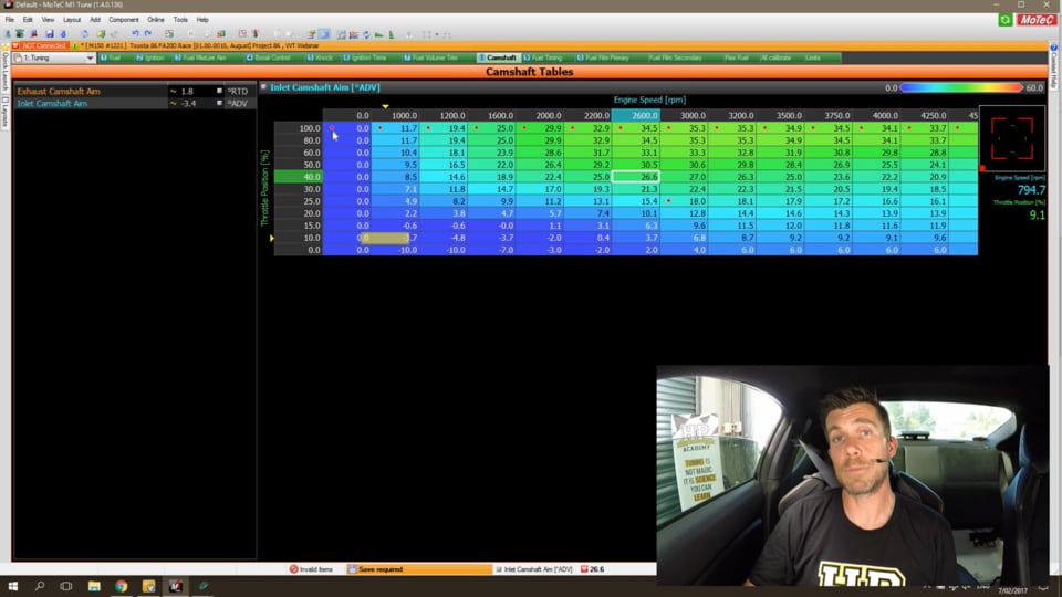
| 05:49 | So this at the moment, we're looking at the inlet camshaft timing table, and you can see the numbers in here vary from, I've actually got negative numbers, a little bit unique for VVT engines and I'll talk about that more shortly, but numbers essentially from about minus 10 through to around about 35 degrees so, again if we were talking about conventional cam spec sheets, an inlet cam, may for example, end up with a cam centerline of 110 or maybe 115 degrees, something like that, so these numbers don't relate to that at all, and this can be confusing, particularly for those people who have dialed in cams, what do the numbers mean, how do we actually utilize these numbers? And, if I just go back to my notes for a second, we'll pull up the next slide. |
| 06:39 | Right if we can look at my laptop screen here, this is what we'd see with the cam events if we look at the exhaust valve lift and the intake valve lift throughout the engine cycle. |
| 06:54 | And we can see that we have our intake lobe centerline here, this is what I was talking about, and if we follow that down, as I said depending on the cam profile where exactly it's dialed in, it might be reasonable to expect that camshaft centerline to be somewhere around 110 degrees after TDC. |
| 07:14 | So this point here, we're on TDC on overlap, so the exhaust stroke has just finished, and as the exhaust stroke finishes the piston ends up at the top of the stroke, at the same time the intake valve is opening, and we move into the intake stroke where we see the piston moves back down the bore, and brings in a fresh charge of fuel and air. |
| 07:37 | Now, when we're talking about the numbers in those timing maps, we're talking about the degrees of advance or degrees of retard from the camshaft's normal position or relaxed position, and in most engines what we find is that the cams will naturally move to their base position, so in the case of the inlet cam, the base position for the cam would be providing maximum retard, and the exhaust valve cam on the other hand will be providing maximum advance, so what we're ending up doing here is essentially spreading these lobe centerlines. |
| 08:21 | And what that does is, when we move the intake and exhaust valve centerlines apart, we spread them, we advance the exhaust cam and we retard the intake cam, this provides us with a minimal amount of overlap here. |
| 08:34 | This provides us with really good idle quality, and the other thing we will find often is, with these designed factory VVT designs, this is generally the sort of position these cams will end up wanting to go back to at high rpm, when we're making maximum power. |
| 08:51 | So that's what we're talking about when we have numbers of 35 degrees in the intake cam timing map for example, this is degrees we've advanced the intake cam, so we've actually moved it this way, we've advanced it, so we've got the intake valve opening earlier, and also closing earlier when we advance the cam. |
| 09:14 | On the other hand, when we have that at zero, we've moved it to the right, we've retarded it, we've got out valve timing events happening as late as possible. |
| 09:23 | The exhaust cam on the other hand works the opposite way, our base position will be maximum advance typically, and then the numbers in the exhaust cam timing map will be retarding the cam, so providing more overlap. |
| 09:41 | So, we don't need to specifically worry too much about the cam centerline values, this is a question I quite often get asked so, how does it relate, what's it all mean? And the answer is it doesn't necessarily matter, what we want to do is simply move the cam timing, and see how that affects the engine's operation. |
| 10:03 | So really, it doesn't matter if we're talking about degrees of cam timing or we're talking about the number of fluffy unicorns in that cam timing map, all we want to do is move in one direction, watch what's happening, and this will help build up a picture of which direction the cams want to move, so it's really important to state that we don't specifically need to know how this relates to the camshaft centerline. |
| 10:28 | Alright, I'll just move back to my notes. |
| 10:32 | Now, the effect of the cam timing, or the effect of moving the cam timing around, how does this affect the engine's operation? Well what it does is it affects the cylinder filling, so it affects the volumetric efficiency of the engine, in essence how much air we're able to cram into the cylinders during the intake stroke, and also how completely we can scavenge or evacuate those exhaust gases out of the cylinder during the exhaust stroke. |
| 11:03 | Now this is where the problem comes in, I said before that fixed cam timing was a compromise, which we now get away from with variable valve timing, and the reason we've got a compromise is because, where we want the cam position is different at low rpm verus high rpm, so for example at low rpm what we want to do is open and close the intake valve very early. |
| 11:27 | Now, this prevents the intake valve, let's just go back to our little cam timing map, we'll go back to our cam timing map on the laptop here, and what we find is that the intake cam actually will be open, the intake valve will be open even after the piston has moved past bottom dead center. |
| 11:54 | So of course, we've got the piston moves down the bore, it's bringing in a fresh charge of fuel and air, it gets to the bottom of the cylinder, the intake valve is still open, but now the piston's moving back up the bore. |
| 12:07 | So as the piston moves back up the bore, understandably what it starts to do is actually push that fresh charge of fuel and air back out into the intake manifold or the inlet ports, which is obviously counter-productive, we're forcing that fresh charge of fuel and air back out into the inlet ports. |
| 12:25 | So, at low rpm where we have low air speed and there's not a lot of inertia from the low air speed and the inlet air moving into the cylinder, what we want to do is we want to close the intake valves earlier, to prevent the piston from forcing that fresh charge of fuel and air back out into the intake manifold. |
| 12:45 | On the other hand though, when we're at high rpm, now we've got high air velocity, and the part here that's really easy to overlook is, that air actually has a mass, hence it has an inertia, and what we want to do is take advantage of that inertia, when we've got that column of air moving down the inlet port very fast with that inertia, what we can now do is close the inlet valve later. |
| 13:13 | So, remember at this point the piston is moving back up the bore, but we're using that inertia of the column of air moving into the cylinder, to cram more air into the cylinder so we're actually overpacking the cylinder with air and fuel. |
| 13:28 | So, that's what I'm saying here, we've got a compromise, at low rpm we want to have our inlet valve closing early, but at high rpm we want to close our inlet valve later, in other words, retard our cam timing, in order to take advantage of that ram effect from the inertia of the air. |
| 13:50 | Alright I'll just move back to my notes again, so, this is the advantage we have with variable valve timing, we can do exactly that. |
| 14:01 | We can achieve high advance values, so we can advance the intake cam at low rpm to get the optimal cylinder filling, but we can still retard the cam timing at high rpm to take advantage of that ram effect. |
| 14:16 | Now, I mentioned that in most cases the cam timing in the normal or relaxed position, so we're not energizing the cam drive solenoids, will have the intake cam at maximum retard and the exhaust cam at maximum advance, remember this gives us minimal overlap and it gives us that good idle quality. |
| 14:38 | The other thing that's important to consider is that these systems are oil pressure driven, so at idle, particularly if we've got perhaps a 600 or 700 rpm idle, we don't have a lot of oil pressure at that idle rpm, so it can be tricky in some applications or some engines to get really good stable and accurate control of our cam position at these low rpms with low oil pressure. |
| 15:07 | Once we get the rpm up a little bit, we find our oil pressure comes up and all of a sudden we can get really good accurate and fast control of our valve timing so, it's a consideration there, generally we're not going to be targeting a lot of cam timing movement at very low rpm. |
| 15:25 | Now the FA20 engine in our Toyota 86 is actually a little bit unique in so much as, we can actually advance the intake valve from the relaxed position or the zero position, and we can also retard it further, it'll actually allow an advance of something about 40 degrees and a retard of somewhere around the region of about 10 degrees so, not completely unique but definitely not normal in my experience. |
| 15:56 | And, the other thing that's worth considering here is while a lot of the engines, the majority of the engines, particularly Japanese engines that I deal with, use a single solenoid for both advance and retard essentially, they're advancing and retarding using a single solenoid or a single output from the ECU, some engines, and in particular BMW springs to mind, use an advance solenoid and a retard solenoid so, the actual setup of the mechanism will vary from one engine to the other. |
| 16:32 | OK, so we've kind of covered off what the system is, how it works and why it can give us benefits in terms of our engine's performance. |
| 16:43 | It's important when we're dealing with dual variable valve timing engines to understand that we're normally going to see a bigger gain or a bigger improvement in the engine's volumetric efficiency from adjustments in the intake cam position, than we will from the exhaust cam. |
| 17:03 | I'll temper that with that is not always the case, I have tuned a few engines that have shown really significant changes based on the exhaust cam position, but normally you will see the bigger change from the intake cam position, and when I get through to the strategy that I apply, you'll see that that's why I focus on the inlet cam position tuning first. |
| 17:28 | The, and that's also, I should point out, why you quite often will see engines where the manufacturers have only applied variable valve timing to one cam, it's invariably the intake cam that gains variable valve timing in those applications, that's because we see the biggest improvement or potential improvement from that. |
| 17:50 | So it's important to understand what the sort of trends that we're likely to be seeing will be, or what we can expect to see will be, let's just jump across again to my laptop screen, and again we've got the inlet cam target map. |
| 18:08 | Now, I want to point out that we've got a little bit of an idiosyncrasy with this particular setup because you'll notice that my load axis here is throttle position, this has something to do with the custom firmware that I have made for our Toyota 86, and I've swapped from using inlet manifold pressure as the load axis for my VE table, to using throttle position. |
| 18:33 | This is a really important point to note, not that you have to use throttle position, but you need to make sure that the load axis for your variable valve timing tables is the same as the load axis for your VE or fuel table. |
| 18:51 | And the reason for this is that any time we're adjusting our cam position, we're affecting the engine's volumetric efficiency, so if we're using, for example, manifold absolute pressure on the load axis for our cam position table, and we're using throttle position for the load axis on our fuel table, there may be, there's a less than perfect correlation between the two under some instances, so we can get situations where the cam timing, hence the VE of the engine, is being affected in one single cell, or varying in one single cell in our VE or efficiency table, oh sorry, our VE or fuel table. |
| 19:31 | So it's really important to make sure that those two axes match, and I've been caught out on a number of occasions, where I've seen base maps from different ECU manufacturers where these are at odds, and, while you can still get an adequate tune, what you'll find is that often you've got weird drivability issues where the engine seems to respond slightly differently on the road or the racetrack to what you saw on the dyno. |
| 19:56 | So, in this instance, this, as I've said, is part of my custom firmware, this is not relevant to the specifics of our webinar, all you need to know is that those axes should be matched, the actual technique of tuning is exactly the same. |
| 20:13 | So what we can see here is, particularly at low rpm we have numbers at zero or very close to, and remember that is the natural base position of the inlet cam, so that's essentially, in most instances, maximum retard, again, our FA20's a little unique here. |
| 20:32 | If we go up to wide open throttle and the mid-range of our map you can see that we're advancing the cam around about 35 degrees so, this is pretty typical, we're going to normally see the camshaft advance to the maximum amount we're going to be using, this will depend obviously from one engine to another but it might be somewhere between maybe 25 and 40 degrees, and that's going to happen somewhere in the mid-range, or mid to low rpm, somewhere between about 2,500, maybe 4,000 rpm. |
| 21:03 | Now if we move across to the right, we can see that as we get up to higher rpm our cam timing retards back, and when we get right up to 8,000 rpm we're essentially right back to our base position. |
| 21:18 | The other takeaway from this table is, notice that we are using a 3D table, I've already kind of mentioned, touched on that briefly, we have this trend with respect to our load, so we've got maximum advance here at wide open throttle, let's call this high manifold pressure, and low to mid rpm, but if we move down to our lower throttle opening so, this would essentially still be lower manifold pressure, we can see that our cam timing retards again. |
| 21:49 | Now this is done here for two reasons, we've got fuel economy as a consideration, we've also got in OE applications the variable valve timing system on a dual VVT engine can be used to create essentially an internal EGR system. |
| 22:07 | So what we're doing is purposely creating a lot of overlap to dilute the incoming charge with exhaust gases, the exhaust gases are inert, can't burn, essentially what it does is actually reduces the volume in our cylinder because there is a volume in the cylinder that's still being taken up with burnt exhaust gas, and this has the effect of reducing combustion temperature, which can be beneficial, mainly for an OE application, in reducing the nitrides of oxygen that are a pollutant, this is an emissions control aspect. |
| 22:46 | Again, our aims in the aftermarket are probably a lot different to the OEs, and generally when I'm optimizing my cam timing, I'm looking solely for changes in torque to guide me. |
| 23:00 | Let's just have a look at that graphically, and you can see that we've got a relatively smooth shape to our cam timing map as well, this is also important. |
| 23:11 | It's really important to remember here that we are tuning a mechanical system, the camshaft physically needs to move in order to advance and retard, and if we've got really large steps in our cam timing, between adjacent sites, so if we've got a cam timing map that looks a little bit like Mount Everest, it's probably questionable as to whether the system will be able to track those changes, particularly when we're accelerating in a low gear, where we can pull through the engine rev range really quickly. |
| 23:43 | So quite often what I'll actually do once I've completed my map in steady state, and I've tuned it for optimal engine torque at each point, what I'll go and do is actually have a look at the general shape of that map, and quite often if I've got some peaky areas I may purposely average those or smooth the map. |
| 24:05 | Now, yes I may be, in some instances, giving away a handful of newton meters of torque, what I am doing is often providing superior drivability, because I've got a cam timing map that the ECU can physically track and achieve. |
| 24:23 | Now let's jump across to our exhaust cam timing map, and essentially looks pretty similar, if I can, right, sorry, I was just trying to get my numerical numbers across, so we've got again the same sort of table, same axes, and we see the same sort of thing. |
| 24:42 | Now remember that this time the exhaust cam is starting from a maximum advance position, so these numbers are actually retarding the cam timing, so in MoTeC lingo both the numbers are positive, in some ECUs you'll see one table will use negative numbers, one table will use positive numbers, but it's essentially just understanding where we're moving from, from that starting point. |
| 25:13 | Right I'll just jump back into my notes now, and we'll talk about how we can actually go about adjusting these cam timing maps. |
| 25:23 | Actually before we do that, I wanted to just touch on, this is something that's come up a few times on the forum, and I've been asked about this before so I'll cover it here, the effect on variable valve timing on turbo charged engines so, obviously we have the ability here to affect our overlap, and the overlap, the optimal overlap that the engine wants is going to depend on the turbo sizing, and in particular what it's really going to be dependent on is the exhaust manifold back pressure. |
| 26:00 | So particularly when we've got very high levels of exhaust manifold back pressure, we'll want to reduce the overlap, and that's going to be beneficial to our engine power. |
| 26:14 | Generally though, when we're looking at the way the exhaust manifold pressure changes as we go through the load and rpm range, what we'll find is that, at low rpm we have relatively low exhaust manifold back pressure, and as we continue through the rev range we see that exhaust manifold back pressure climb. |
| 26:35 | So generally we will still be targeting a reasonable amount of overlap through the mid-range, but as that exhaust manifold back pressure climbs at higher rpm, we'll want to reduce that, and again the optimal mapping is going to depend on your engine and your turbo charger sizing, however, it doesn't really matter what that is, those are fixed aspects that unless you're prepared to change the turbo charger, obviously are outside of your control once the engine is on the dyno. |
| 27:06 | So the same techniques that we use in order to optimize the cam timing for a naturally aspirated engine, exactly the same as what we're going to be doing on a turbo charged engine, so it doesn't really matter. |
| 27:19 | Now, we're going to go through the tuning strategy and we're going to have a look at that being applied, after that we will go into some questions and answers so, if you do have anything you'd like me to cover, anything I've talked about that you'd like me to expand on, please ask that in the chat, and then Colin will be able to transfer that through to me at the end. |
| 27:43 | OK so, the strategy that I go through, we've got essentially eight steps here that I'm going to cover. |
| 27:49 | And, in the very first step, what we want to do is confirm the mechanical safety of the system. |
| 27:57 | Now, I'm talking here really about, in a professional tuning environment, where you've been brought a car that is completely unknown to you. |
| 28:05 | Now, when I'm talking about the mechanical safety of the system, obviously when we can advance or retard the cam timing, this can potentially result in catastrophic damage to the engine, if we get to a position where the valves contact the pistons or potentially the valves contact the other valves. |
| 28:25 | Now, that's not going to happen if you're tuning a stock OE style variable valve timing system, these are designed so it's impossible to end up with valve to piston contact, there are mechanical stops incorporated in the cam pulleys, that simply prevent the cam being advanced or retarded to a position where it's going to end up with mechanical contact. |
| 28:51 | So, on an OE system we're safe, we don't have to worry about that, however if we've got a modified engine and particularly if the cam profile has been severely altered, in that situation obviously anything goes so it's important to cover our bases and make sure that whoever's built the engine has done their job properly, and can confirm that there is no chance of mechanical contact. |
| 29:18 | If there's any sort of uncertainty there, then it really needs to be put back on the customer. |
| 29:24 | Quite often with very aggressive cam profiles we still want to retain the variable valve timing mechanism, it's not uncommon to modify the cam pulleys, and physically put locks or stop outs that reduce the amount of cam travel, in order to make sure that the engine is mechanically safe, and this obviously needs to be done during the engine assembly process, it needs to be dummy built, the valve to piston clearance needs to be checked, and we need to see how much movement we're able to get away with. |
| 29:57 | I'll just cover off here quickly, it's slightly off this particular topic but, you'll quite often notice when we've got a factory VVT engine that has been heavily modified for either circuit racing or perhaps drag racing, a very specific function where it's only going to be used across a narrow rev range, quite often these engines, when we want a lot of power, we're going to be putting in a much more aggressive cam profile in them as well, and with a larger cam profile with more lift and more duration, this obviously reduces our potential to adjust the cam timing or move that cam timing, so it's not uncommon in these applications to do away with the variable valve timing mechanism altogether, and accept the fact that we're going to be giving away some low rpm performance, that's obviously not something that's critical for a high rpm drag engine, we're looking about, looking at the performance just across perhaps 1,500 to 2,000 rpm of the rev range, and we're going to be optimizing the static cam timing for that only. |
| 31:04 | Alright, so I'll move back to our strategy now, so that's our first step, we need to know before we get started that the engine is mechanically safe, that we're not going to be able to advance the cam into a position where it's going to contact the piston. |
| 31:20 | Now the next step is we need to calibrate our cam control system, and what I'm talking about here is telling the ECU where the cam positions are. |
| 31:32 | Now the MoTeC M1 ECU actually makes this incredible easy for us because the cam timing data, all of the variable valve timing data actually is incorporated in the ref/sync mode so, for us, as an end user, there's a limited amount of work to do. |
| 31:50 | I'm not actually going to go into the setup functionality here, we'll do this in a further webinar, but what we want to do is confirm that the ECU is able to control the cams correctly, and this also includes making sure that the PID settings are correct, what we want to do is make sure that the cam timing is able to track properly. |
| 32:15 | And what I'll do is I'll just get our engine running here, and we'll have a look at what that looks like. |
| 32:21 | OK, so if we can jump into my laptop again, and I'll just, just got, I'll just get back online, save that one, and what we'll do is we'll just have a look at our cam timing moving while I've got the engine running here. |
| 32:43 | Right so, we'll go across to our camshaft worksheet, and, we can look at this on our time graph, and what I'll do is I'll just fullscreen this. |
| 32:54 | So, we've got a few parameters here that are of interest, we've got our Engine rpm, we've got our Throttle Position and our Inlet Manifold Pressure, then our next two groups we've got our Inlet Cam Bank 1 Position, and we've got our Bank 2 Position, obviously on our Toyota 86 we've got a horizontally opposed boxer engine, and you can see that in blue we have our Camshaft Aim. |
| 33:18 | So the Camshaft Aim is what's coming from the tables we previously looked at, and what we want to do is make sure that the actual cam position is tracking our target, and what I'll do is I'll just move the throttle around and we can see that the cams are able to track correctly, so let's just have a look at that now, we'll just let it come over and I'll pause the time graph. |
| 33:46 | OK so, in this position here, this is where I gave the throttle a blip, and we can see that our cam positions are both tracking our target really closely. |
| 33:56 | It's one of those areas where we need our setup, our configuration to be really accurate and we need our PID control algorithm dialed in, so that our targets are tracked really quickly. |
| 34:09 | Any time there is a discrepancy between our target cam position and our actual cam position, then that's going to be affecting the cylinder fill or the engine's volumetric efficiency, it's going to be making it harder for us to maintain a really consistent and stable tune, so the better the system is able to track, the better our results are going to be. |
| 34:32 | That being said, let's just have a look here, it's important to understand what is realistic, again, just understanding that this is a mechanical system that isn't able to track instantaneously, so it's something that a lot of tuners forget about, there is a lag, there is a time delay on the camshaft physically being able to rotate. |
| 34:53 | So we can see in this position here, remember the blue line is our Camshaft Aim, as I've come off the throttle we can see our Camshaft Aim drops away, and in this particular point here we can see our Camshaft Aim is sitting at 15 degrees, and both of our cams have lagged a little bit, they're sitting at 19.8 and 20.2 degrees, so these are the sort of things, and that's relatively minor, these are the sort of things we need to consider there, make sure that our cam system is actually able to track the target properly first. |
| 35:27 | OK so, once we've done that, then we want to generally start, my preference is to start with our exhaust cam timing at zero, and focus on our inlet cam timing initially, remember, the intake cam is often going to show the largest performance improvement. |
| 35:46 | Now, there's a process that we're going to have to go through here, because remember, every time we adjust our cam timing, we're going to end up affecting the engine's volumetric efficiency. |
| 35:59 | In turn, what this is going to mean is that we will have to adjust our volumetric efficiency table, or our fuel table, and we may also at the same time need to adjust our ignition timing. |
| 36:12 | So my strategy when I'm tuning a VVT engine is until I've got my inlet cam and my exhaust cam positions relatively close to perfect, I'm only going to approximately tune the fuel and ignition tables, I'm not going to waste a lot of time getting my lambda absolutely pinpoint accurate, what I'm going to do is just get them in the ballpark and close enough, and then, once I've actually got my cam timing 100% optimal, at that point I'm going to then go through and optimize and finalize my cam, my inlet, my fuel and ignition. |
| 36:56 | Alright, we'll carry on from where I left off so, I'd just discussed the fact that we want to get our cam timing accurate before we worry about being really, really fussy with our fuel and our ignition so, otherwise all you're going to end up doing is spending a lot more time than is absolutely necessary doing your fuel and ignition because it's an iterative process, you adjust the cam timing, you then need to adjust the fuel, and potentially the ignition, then you'll come back, make further changes to your cam timing, and so on and so forth. |
| 37:31 | Now, with the M150 on our Toyota 86, we've got the closed loop fuel control system operating as well so, this makes my life a little bit easier because I can simply leave the closed loop fuel control to look at the air fuel ratio being measured in the exhaust, and make adjustments as necessary, so this keeps my lambda on target while I'm adjusting the cam timing, and making changes to the engine's volumetric efficiency. |
| 38:02 | There are two aspects though that we want to be monitoring while we are optimizing our cam timing, so this is important to keep in mind, the two parameters that we're interested in are our engine torque, which is coming from the dyno, and our air fuel ratio, and these are going to give us the clues we need to understand whether we're going the right way with our cam timing. |
| 38:26 | So what we're really looking for here is our torque to increase, and at the same time if we increase the engine's volumetric efficiency and we're providing the same amount of fuel, then obviously we're going to find our air fuel ratio goes lean. |
| 38:42 | So this is where it's a catch-22, if we were running in open loop fuel mode, what we would see is our lambda trace would start to move lean, that's our guide there. |
| 38:53 | If we're running in closed loop mode that gives us one less thing to do because it's taking care of our fuel tuning, roughly, while we're getting our cam timing dialed in, but we want to take note of what's happening to our closed loop fuel trims, to give us that same indication of what's happening with our lambda. |
| 39:11 | Alright, so what I'm going to do now is we're just going to have a quick look at some steady state tuning, and I'm going to go through, I'll just get our engine running here in fourth gear, I'm going to go through essentially a torque opimization test here on our Mainline dyno. |
| 39:29 | Now I'll just get our engine up to about 3,000 rpm, before we do this. |
| 39:41 | OK so, we'll just jump into my laptop software for a second, we'll just have a real quick look at what we're going to do here. |
| 39:49 | Let's just bring up a target, OK, so we've got our little target here showing exactly where we're operating in the cam timing map. |
| 40:00 | We can see that we're sitting at 25% throttle, 3,000 rpm. |
| 40:04 | What I'm going to do, just for the sake of simplicity, is I'm going to start by highlighting all of the cells around that particular cell, and I'm going to set them to minus 10 degrees, now that's the limitation of our travel, that's as far as we can actually move the cams, and what I'm going to do is go through and adjust our cam timing, advance the cam timing all the way to 40 degrees, and we'll do our torque optimization test. |
| 40:33 | Let's jump across to our laptop, oh sorry our, now I'll just get us back there, excuse me, sorry. |
| 40:45 | Just managed to press the wrong button on my dyno. |
| 40:50 | OK, what we'll do is we'll bring up a torque optimization test so let's jump across to the dyno screen, and we'll just look at the dyno screen while we're performing this particular test. |
| 41:05 | And, I'm going to just change the setup so that the numbers are going to make sense, please bear with me. |
| 41:15 | Inlet Cam Position that's what we want, OK. |
| 41:21 | So we've got our torque values on the vertical axis there of our torque optimization test, and we've got our camshaft position coming through from the M1 ECU via CAN, so what I'll do is I'll just ourselves stable here, and I'm just going to click Begin, and this is really no different to the test that I do for MBT timing. |
| 41:47 | So, all I'm doing here is advancing the cam timing by a degree every second, and this is going to give us a relatively messy trace unfortunately, so once I've finished this trace, we're going to go through and see what it sort of visually looks like and we're going to have to do a little bit of mental averaging to get an idea of what's actually going on, but hopefully I'm gonna be able to get a nice enough trace to sort of start picking a bit of a trend. |
| 42:17 | So you can see we're getting up to around about six degrees of cam timing now, so we'll just keep going through, and hopefully if my original map was approximately right, we're going to see that we should make peak torque somewhere around about 17 or 18 degrees, I think that was about the value I had in that particular cell. |
| 42:37 | And you can see that we are seeing the torque being measured by the dyno pick up, so, we're up around that 16, 17 degrees now, 18 degrees, 19 degrees, so we're gonna keep going, we've seen our torque pick up. |
| 42:56 | At the moment the dyno's showing us that we've made peak torque at about 19.8, no, we've jumped up to 22.8 degrees, it is really important as well when you're doing one of these tests to make sure that you're really consistent with your throttle position, otherwise it's very easy to negatively influence and essentially ruin the test. |
| 43:16 | So we're getting up to 30 degrees now, and we're starting to see that our torque is dropping away again, so this is where I'd say it's a little bit like the MBT timing technique that I've shown on the dyno where we look at what's happening with our torque as I adjust the ignition timing. |
| 43:34 | Alright, I think that's shown enough of our trend now so I'm just going to back out of that, and, we'll have a look at what we've got drawn on our laptop screen. |
| 43:44 | So, again, it's a relatively noisy trace which is important to understand, so what we're looking for is sort of an average trend through here, so we can see that, minus 10 degrees we started somewhere around about 85 newton meters, and if we sort of ignore the individual blips in this, we can see that somewhere around about 20 to 22 degrees of cam timing, it's given us about 102 newton meters, as we've gone past 22 degrees, you can see that we've dropped back off, back down to around about 90 newton meters. |
| 44:15 | So this is the technique that we're using, obviously your dyno may not have the torque optimization test, and in reality I'm not using this to optimize every single site in our table, this is just a really great visual way to show us exactly how the cam timing is affecting the engine torque, and it's affecting the engine torque because it's affecting our volumetric efficiency. |
| 44:42 | Now, at the same time, the fuel trims were active there so, what we can see, let's just, actually I'll jump back to our fuel table, no, I'm not gonna be able to easily show that, let's go to our cam. |
| 45:00 | Alright so, what I'm going to do is just go to the start of our run here, so you can see there on our time graph we're sitting at 3,000 rpm for that whole experiment there, that whole test, we're spinning about 26% throttle, and if we can just ignore our exhaust cam for the moment, you can see at the start of that test we're sitting at minus 10 degrees, remember that's where we started, at the end of the test you can see that that jumps up to, I stopped at about 36.5 degrees, and what we're looking for is the trend in our closed loop fuel trim, so that's being displayed down here by this bar graph so, let's look at that trend and see what we can tell, hopefully it's going to back up what we saw with our torque. |
| 45:46 | At the start, at 3,000 rpm, minus 10 degrees, you can see that we have a closed loop fuel trim of minus 2.7%, so the ECU is pulling 3% fuel out essentially, so, we're a touch rich. |
| 45:59 | As we move through, now let's get up to, around about 20 degrees, remember this is where we saw peak power, now look at our closed loop fuel trims and see what that's showing us, now the ECU is adding 4.8, let's call it 5% fuel, so between our starting point and our optimal cam angle for this particular cell, we've got 8% trim in our fuel, 8% difference in our VE table, that's quite a large change. |
| 46:28 | Now as we continue to advance the cam timing and we go too far, you can see once we get to 34, 35 degrees, we've gone negative again on our closed loop fuel trims, we're now pulling 1.1% fuel out. |
| 46:42 | So of course, as I've mentioned, if we weren't running closed loop fuel control here, we would see our lambda start a little bit rich, it would move excessively lean, and then it would start moving rich again. |
| 46:54 | Now, one point to consider here, is that if you are running in open loop mode, we do need to be a little bit wary of how much our air fuel ratio is moving around. |
| 47:07 | And the reason I say this is, if you aren't adjusting your fueling as you adjust your cam timing, to keep the fueling roughly in the ballpark, then what we can find is that the effective improvement in volumetric efficiency at 20 degrees of cam advance, is masked by the fact that the engine is perhaps now running at 1.08 lambda, and it's too lean so we're actually losing torque because the air fuel ratio is too lean, so it's really important to make sure that if you are manually adjusting it, it becomes an iterative exercise. |
| 47:43 | What we're going to be doing, is we're going to be starting with relatively conservative ignition timing, we're going to adjust our cam timing, then as we adjust our cam timing we're going to keep track of our fueling, and this may need us to swap backwards and forwards between the fuel and the cam timing maps to keep track of everything. |
| 48:03 | Now, when we are tuning the cam timing I do treat this a little bit like any other aspect, whether we're tuning fuel or ignition, and I'm going to split my tuning up into two areas. |
| 48:15 | We're going to deal with steady state tuning, and I use this to deal with the cruise, the light throttle areas, the part throttle areas of the map, and up into the transition areas as we come up to full power, but then under wide open throttle, we obviously don't drive and tune these areas in steady state, so it's easier to transition across and start looking at tuning those areas in ramp runs. |
| 48:40 | So what I'm going to do now is we'll jump back into my laptop screen, and we'll just unpause our time graph, and what I'm going to do for a starting point is I'm just going to simply set our, all our wide open throttle operating areas here to zero degrees. |
| 48:59 | So, what this will do is just mean that we've got a fixed cam timing of zero degrees, and let's start doing some ramp runs here on our dyno and see how we can use the dyno to help us optimize our cam timing under wide open throttle ramp run conditions. |
| 49:17 | So what we'll do is we'll just get our engine running, in fourth gear again, I'm not gonna do this completely here, I'm just gonna give you a few runs so you can see the sort of trends that we're going to end up with. |
| 49:30 | Alright, I'm going to go to full throttle and we'll do a run through to around about 6,000 rpm. |
| 49:50 | OK, so that's our first run done, 148 kilowatts, I'm not really interested right now about the outright power, what we're going to look at is how it compares to our subsequent runs. |
| 50:00 | Before we do that though, let's just jump back into my laptop software for a second, and remember, at this point I am not making adjustments to the VE table, but what's important to see is the effect on our fueling. |
| 50:13 | So let's have a look here, let's just have a look at 4,250 rpm, you can see in our time graph here, let's just fullscreen it just briefly, at the bottom we have our lambda target and our measured lambda, and you can see through most of this area under wide open throttle, we're actually still surprisingly close to our target, but don't be fooled, the only reason we're so close to our target is because of our closed loop trim, and particularly at 4,150 rpm here, we've got a negative trim of almost 20% to keep our lambda as close to target as it's getting. |
| 50:51 | OK, so what we're going to do now before I jump back out of my laptop screen, let's just set our entire wide open throttle operating area to 10 degrees. |
| 51:02 | Jump back across to our dyno, and what I'm going to do now is we'll save this run, and what I'm going to do is we'll call it VVT 0 degrees, just so we can reference that a little bit later on. |
| 51:15 | OK, and what we'll do is we'll show our last run, just so we can see it overlaid in real time. |
| 51:21 | OK, let's do our second run now and we'll see what our results are. |
| 51:30 | OK we're back in fourth gear, so we've got 10 degrees cam timing now, let's go and start our run. |
| 51:49 | OK, so we got our second run complete and straight away you can see that, just about everywhere except at the start of the run, we've seen a significant increase in our engine power. |
| 51:59 | Now obviously we're looking at power here but power is calculated from torque so obviously it also means we've seen an increase in torque everywhere. |
| 52:08 | Let's do one more of these runs, we'll save this one and we'll call it 10 degrees. |
| 52:13 | Let's jump back into our laptop software, and, what we're going to do this time is set our entire wide open throttle operating area to 20 degrees. |
| 52:23 | Right, back across to our dyno, let's do our third and final run, and then we'll see what we can do with this data. |
| 52:36 | Alright, let's start our third run. |
| 52:52 | OK, so we've gone from about, I think our first run was somewhere around about 148 kilowatts to 165, just through our cam timing. |
| 53:01 | Let's just save this run, and we'll have a look at all our three runs together. |
| 53:08 | Now, because I've only done a partial run here and we've only done three runs, we're going to see the effect but I'll just have to explain how we actually use this technique. |
| 53:19 | So we can see there on our dyno screen, we've got two pieces of information being shown, at the top of the screen we've got our three power runs, so this is our power in kilowatts at the rear wheels, below this I've also plotted our cam position for those three runs, so, what we can see straight away is what cam timing position related to what. |
| 53:40 | Now, if we had continued and done runs at 30 and 40 degrees and we'd gone all the way through to 7,500 rpm, what we're going to find is that we end up with our lines overlapping at some point, and this helps build us a composite picture, what we can do is simply go through the plots, and pick the point where, for example, 30 degrees makes more power than 20 degrees, or 40 degrees perhaps makes more power than 30 degrees, and this allows us to build up a composite shape to our VVT maps under wide open throttle conditions. |
| 54:19 | Again, I'll just reiterate, this process needs to be iterative in its nature, we're changing our cam timing and hence that will also require us to change our fueling and also potentially our ignition timing. |
| 54:34 | Alright, so once we've got our inlet cam close, then the next technique is we're going to go through and adjust our exhaust cam timing. |
| 54:46 | So, again, this is why I've said it's not important right now to be ultra fussy with getting our fueling and our ignition timing absolutely optimal, what we want to do is get our intake cam dialed in closely, and we want to get our exhaust cam timing dialed in closely, once we've done that then we can go back, once everything's accurate, we can go back and we can change our fuel and ignition timing. |
| 55:11 | Now there's one more step, I'm not gonna go through the exhaust cam timing here because realistically it is just a rinse and repeat of what we've seen here, we're simply going to go through and make some adjustments to our exhaust cam timing, like we've seen with the inlet cam timing, and we're going to see where we end up with peak torque, where our torque is optimal, and that's, once we've got our torque optimal, then we're pretty much done. |
| 55:43 | One final step though with our cam timing is we've started with our intake cam, then we've gone through and we've got our exhaust cam where we think it needs to be, I go one step further though and I'll go back and I'll revisit my intake cam timing one more time, and just perhaps at this point we should be already very close, I'll do one final set of tests where I'll advance the cam timing five degrees, perhaps retard it five degrees, and make sure that by bracketing the cam position like this, that I am still optimal. |
| 56:18 | And the reason for this is we can obviously advance the intake cam and retard it independent of the exhaust cam, we can advance the exhaust cam and retard it independent of the intake cam, or we can advance and retard the cams together, and depending on exactly the process we go through here, this will affect our valve timing events relative to each other, we're also affecting our overlap. |
| 56:45 | So, by going through the process of doing our intake cam, following that with our exhaust cam, and then finally going back and revisiting the intake cam, this is going to give you 99%, 98% of the potential results that are there, in a time efficient manner. |
| 57:05 | Finally, once we've actually got our cam timing maps 100% to our liking, we can then go through the process of optimizing, finely optimizing the fuel and ignition and making sure that's all completely accurate. |
| 57:23 | OK, so hopefully that's given you some insight there, hopefully that hasn't confused you more than you already were before you started this, we will move into questions and answers really shortly, so this will give you the opportunity to get me to clarify anything that you perhaps didn't understand correctly. |
| 57:40 | But I'll just go over that process again, from start to finish, so we want to make sure that our valve timing system, our cam timing system is mechanically safe before we get started. |
| 57:52 | Once we've done that we want to then make sure that the control system is functioning, so that the ECU is able to physically track the cam targets that we're asking for. |
| 58:04 | Now, one other thing actually I haven't mentioned there as well is when we are tuning the VVT system, it's important to find out the extent of travel of the cams. |
| 58:16 | Now what I mean by this is, depending on the engine design, will depend on exactly how much we can move the cams, maybe it's 35 degrees, maybe it's 50 degrees, but we need to find that out, and make sure that we're always targeting an achievable cam position. |
| 58:35 | And what I mean by this is if our inlet cam, for example, limits us to 40 degrees of advance, if we're then requesting 45 degrees for example, or even 41 degrees, what's going to happen is that the PID control algorithm will not be able to reach its target, its going to be physically stuck on that stop at 40 degrees, and it's going to be trying to get to 41 or 42 degrees. |
| 59:00 | And what happened under these circumstances is that the integral element of our PID control will continue to drive the solenoid duty cycle harder and harder, in order to try and meet our target which is impossible. |
| 59:17 | And the upshot of this is when the cam target drops back into something that is achievable, we get this situation called integral windup, and what it does is it creates a lag or a delay as the integral element has to reverse and unwind, before the system can again achieve our aim, so it's really important as one of your first steps, just to make sure that you're targeting achievable and accurate cam angles, don't try targeting something that the mechanical system can't achieve. |
| 59:49 | Then once we've got our system operating we're going to start with our exhaust cam timing at zero, and we're going to focus on our inlet cam timing first. |
| 59:58 | We're going to optimize our inlet cam timing, again looking at feedback from torque and air fuel ratio, remembering at this point there's no requirement to be overly fussy with our fuel and ignition, we just want numbers that are going to get us in the ballpark. |
| 01:00:12 | Once we've done our intake cam timing under steady state and wide open throttle ramp runs, we can complete the same process for our exhaust cam timing. |
| 01:00:21 | And finally once we've done that we'll go back, revisit our intake cam timing, try advancing the cam timing five degrees, retarding it five degrees, just bracketing that initial position to ensure that our initial position was accurate, or maybe we'll find that we do need to adjust our cam timing slightly, now that our exhaust cam timing is optimal. |
| 01:00:42 | Finally, once we're happy with our cam timing, the last step is to go through and accurately optimize your fuel and ignition. |
| 01:00:51 | And one other aspect that's important to cover here is that with our cam timing maps, because we will usually see a smooth and consistent trend in those tables, as you've already seen inside the M150 ECU, quite often we don't need to be too fussy with our zoning or our breakpoints in those tables, it's sufficient to have relatively coarse breakpoints, and we can also use interpolation to help fill out the tables so, that's simply going to speed up the process and we're generally going to want a smooth shape to those tables as well. |
| 01:01:31 | Alright, we'll move into some questions now, let's see what we've got. |
| 01:01:42 | Gustavos has asked, "Making this ECU is not going to "throw us a check engine light". |
| 01:01:48 | OK, not quite sure what you're quite referencing there so, with this obviously being an aftermarket ECU, then we've got a lot of control over what will and won't cause a check engine light, for example. |
| 01:02:02 | What we want to do is make sure, as I've just touched on, that our cam timing targets are achievable, and this also goes back as well to that second step in our process, making sure that the cam timing system is tracking. |
| 01:02:17 | Quite often, if you are tuning a factory ECU, an OE ECU reflashing, you'll find that the factory ECU will be very fussy on the allowable discrepancy between the cam target and the cam positions, and often, particularly if you've heavily modified the engine, this can result in some discrepancies and this can result in problems with check engine lights, but typically not an issue that we should be considering, or not an issue we should be having problems with in an aftermarket ECU. |
| 01:02:50 | CypherMonk said, "When you have an engine "with larger aftermarket cams, "can I cover strategies for getting them to idle nicely?" OK so, I think here it's really important to be realistic about what you're expecting. |
| 01:03:06 | If you go and fit a cam with, you know, an advertised duration of 270, 280 degrees or larger, then inevitably you're going to be increasing the overlap over what a factory cam profile is going to provide. |
| 01:03:21 | Now that overlap is going to necessitate a slightly lopey and more aggressive idle, and, if you're going to go to a larger cam profile, you need to be very mindful of that, if you don't want to adversely affect your idle quality, you're only going to be able to get away with a relatively mild upgrade in cam profile. |
| 01:03:45 | That being said, with a VVT system we do have a little bit more flexibility obviously, and generally, I've sort of touched on this in the body of the webinar, what we want to do is minimize our overlap if we want a really good, stable idle quality. |
| 01:04:00 | The other aspect to consider here is, once we've gone to a more aggressive cam profile, quite often we're going to need to increase the idle speed, and that's something that's often overlooked, you know if you've got a factory engine, that's happily idling at 650 rpm with the stock cam, you go and put a really aggressive cam with, you know, maybe 290, 300 degrees of duration, advertised duration in that engine, and, there's no way in the world it's going to idle at 650 rpm. |
| 01:04:32 | And to give you some perspective here, in the LS tuning world, the shop car that we used to have, we used a relatively aggressive cam profile, I can't quite remember the specific numbers now, which isn't useful I know, it's about as big a profile as we could fit in a stock, unopened, L98 engine, but we went from a 650 rpm idle, 600 rpm idle, to about 850, 900 rpm in order to get a good idle quality. |
| 01:05:02 | If we look at something much more aggressive like my 4G63 drag engine, that wouldn't idle below 1,800 rpm so, you do need to be a little realistic with what you're trying to achieve. |
| 01:05:15 | A real frustration for me was, many years ago I was involved with a Toyota 3UZFE race engine that was built and developed by Toyota Racing Development in the US for the Grand-Am series over there. |
| 01:05:30 | A few of these engines were brought into New Zealand by Toyota Racing New Zealand, and they were used in the NZV8 touring cars in a Toyota Camry Tube Frame race car. |
| 01:05:41 | And I was tasked with tuning one of these, I'd never seen the engine before, I got the engine running on a Vi-PEC ECU and, I wasted about an hour trying to achieve what I considered to be a good idle quality, and in the end the best I could do was achieve about a 1,600 rpm idle, which for a five liter V8 engine is a pretty damn high idle. |
| 01:06:04 | And I ran this past the engineer in charge of the project, and he said that the TRD literature that came with the engine said that the idle speed needed to be 1,800, information that would have been really helpful to me if I'd had that before I started trying to achieve a 1,500 rpm idle but, there you go so, be realistic. |
| 01:06:24 | Long-winded answer to your question, hopefully there was some information in there that was actually useful in answering that question. |
| 01:06:34 | Gustavos has asked, "I have a Lancer Ralliart 2004, "2.4 liter with just one cam, but this engine has MIVEC, "how will that work with the MIVEC?" OK, it's not an engine that I am familiar with, the MIVEC on that would be a variable cam timing I will assume like we've talked about here. |
| 01:06:56 | With a single cam system, it's still possible to have variable valve timing, but essentially here what we're doing is, we are affecting, we're advancing and retarding the cam, the intake and exhaust cam profile simultaneously, so in this situation, it's possible to advance and retard the cam, it is not possible to affect or adjust our valve overlap. |
| 01:07:20 | So the process however is exactly the same as what we've looked at, your process however is much simpler, because you've only got one table to adjust there. |
| 01:07:32 | Barry G says, "Seems like so much work, "how do you charge a customer for all that effort? "Approximately how long does a tune like this "take to complete?" In all honesty Barry, it doesn't take as long as it may seem, and often as well, we're going to be dealing with a car that may already have a developed map, so obviously this particular webinar has been based on the M150 Standalone ECU platform, so, if you are tasked for the very first time of tuning a Toyota 86 on an M150, the base maps developed and supplied as part of the Toyota 86 package, are already actually very very well developed so, instead of needing to start from scratch, we can simply tweak and adjust the maps delivered in that package. |
| 01:08:24 | Likewise if we're tuning an OE ECU, we wouldn't be zeroing those timing maps out and starting from scratch, we would be adjusting or optimizing from that starting point, so that obviously cuts down our workload. |
| 01:08:38 | But in reality, even tuning from completely zeroed out tables, if we were developing a map on an engine we'd never seen before and had no start point, it really doesn't take as long as perhaps it might seem, and a lot of it comes down to as well, how fussy you want to be. |
| 01:08:56 | Yes, you could set up your variable valve timing tables with 250 rpm breakpoints and perhaps 10 kPa load points, and create a large three-dimensional table and then tune each individual cell, one at a time, and yes that's probably going to give you the best possible results, however, as I've just mentioned a little earlier, generally because the trend and the shape in those VVT timing maps is pretty consistent, we can actually be relatively coarse with these timing maps. |
| 01:09:27 | And also, we can interpolate between cells so, we can perhaps jump ahead a couple of cells and then interpolate in between, because we've got that general trend or shape, it's a little bit like building up a fuel map or an ignition timing map, we can build up that map, copy that ahead, and then that's going to speed up the process as we move through so, really it isn't a lot more time-consuming, it's obviously more elements in there, and you do need to charge your customer accordingly. |
| 01:09:57 | We charged, in my old business, we charged more money for tuning variable valve timing engines because yes, they do take longer. |
| 01:10:06 | You've asked, "Approximately how long "does a tune like this take to complete?" Pretty difficult to answer, I would say that with a standalone ECU if I was starting from scratch on the dyno, I would probably allocate somewhere in the region of four hours in total for that work, some will be a little bit faster, some will be a little bit slower. |
| 01:10:29 | Alright, that looks like it's taken us to the end of our questions, so hopefully that's given you a better overview of dual variable valve timing and hopefully also, more importantly, a strategy that you can take with you and apply in your own tuning. |
| 01:10:43 | Thanks for joining us, if you do have any more questions please ask those in the forum and I'll be happy to answer them there. |
| 01:10:50 | We'll see you all next time. |


