326 | CAD Files for CNC Production: Essential Tips
Summary
One of the key advantages of CAD is being able to get our designs manufactured, specifically using CNC methods. For this we'll need to provide files to our chosen 3rd party manufacturer, but how do we know what we'll need? In this webinar, we'll cover the standard file formats for common CNC manufacturing methods, as well as how to generate this inside CAD software like Fusion 360.
| 00:00 | - Hey team, Connor here from HPA, welcome to this week's webinar. |
| 00:04 | So this week we're going to be talking about CAD files for CNC production. |
| 00:11 | So this is specifically around, you've designed something in CAD for your motorsport build or any automotive application and then you want to get it made by a CNC manufacturer, third party CNC manufacturer. |
| 00:26 | So today we're going to discuss what files you're going to need for each CNC manufacturing process, be it laser cutting, CNC milling or even 3D printing and I'm also going to show you some examples inside Fusion 360, but it is the same for most CAD software, of how to produce those files and then we're going to talk about some important considerations around computer aided manufacturing, CAM for short and DFM which is design for manufacturing. |
| 00:57 | So we'll get into it, and the first thing that we should probably talk about is technical drawings. |
| 01:02 | So technical drawings are really necessary for use when we're getting parts made manually, so not using CNC methods. |
| 01:14 | You're going to have to have a technical drawing, unless the manufacturer has, also has access to some CAD program and can get a good look at your CAD file. |
| 01:25 | But otherwise, technical drawings are really the best way to go about this, stating down everything that's important about our design, all the dimensions, finishes, threads, everything that they need to know to be able to make it. |
| 01:41 | In terms of CNC manufacturing, where technical drawings come in is they're really great for checking the finished part. |
| 01:50 | So things like quality control, basically after it's done, being able to check the dimensions of the part, we can reference this to a technical drawing and make sure that the part has basically been made correctly and it's within the spec, so if we specify tolerances, like the width of something needs to be 50 mm +/- 0.5 mm and we measure it at 49 mm then it's obviously out of spec. |
| 02:18 | So really good for that. |
| 02:20 | Also often required with CNC manufacturing processes to call out things like threads, like the thread in a hole. |
| 02:30 | So sometimes when we model something in CAD we will add a thread to something but it won't actually model it, in some cases we can choose to do this or choose not to do it, basically put short because it increases the file size and complexity. |
| 02:47 | So sometimes we'll leave it off and then when we get to our technical drawing, we can just specify that hey this thread here is an M10 x 1 for example and when the machinist is maybe machining our part, they can then program that into their tool path. |
| 03:06 | But when we are doing, working with a third party CNC manufacturer, they're always going to require some type of CAD file of course. |
| 03:16 | So obviously if we design that, we're going to be sending them that CAD file rather tha them doing the work for us which of course is going to cost a lot more. |
| 03:26 | One of the key benefits of learning CAD and doing the work ourself. |
| 03:31 | So moving on from that. |
| 03:33 | Different CNC manufacturing processes. |
| 03:36 | We'll start with maybe one of the most simple being 2D cutting. |
| 03:39 | So here we could be talking about laser cutting, water jet cutting, plasma cutting and in some cases routing as well can be useful to the cutting. |
| 03:50 | And this is very commonly used for things like sheet metal parts, laser, water jet and plasma cutting. |
| 03:59 | So the standard file that we'd send to a third party manufacturer for this is generally a DXF file and that's a drawing exchange format file. |
| 04:09 | And it's basically an outline of the drawing, including, well an outline of the part, including things like holes and stuff as well but it's just a very simple line drawing. |
| 04:20 | Some manufacturers will also be able to work with a DWG file which is also a very standard drawing format and in some cases PDF files as well. |
| 04:31 | With a sheet metal part for example like a part that has bends or forms or flanges on it, this is just to create the 2D part so when its in its unbent flattened form. |
| 04:50 | Because obviously that's what the CNC process does, laser cutting is not going to bend the part for us so if we have a part like that, we flatten it, we get it made like that and then when we have it, we might apply the bends ourself or maybe we can provide the manufacturer with a technical drawing that shows them how to create the bends that we want in it. |
| 05:15 | But today we're specifically talking about just producing the flat part. |
| 05:19 | So what I'll do is I'll jump into Fusion 360 and we'll quickly just model a sheet metal part and I'll show you how to produce the DXF files from that. |
| 05:32 | So we've got Fusion 360 open here and I'll just create a sketch on this plane and I'll just make a simple rectangular part. |
| 05:46 | Won't dimension anything, oh that's probably a bit big. |
| 05:52 | Just put a few holes in it. |
| 05:57 | Could be for anything and then let's just say we'll round the corners as well. |
| 06:06 | Sorry clicking the wrong things, we'll leave it as it is there. |
| 06:09 | So then we can go into our sheet metal tools and click flange and just basically create a sheet metal flange. |
| 06:23 | We can also sketch on this, really quickly and just bang in a line there and we will bend stationary side and we'll just bend that up like that. |
| 06:41 | So simple sheet metal part with a few holes in it. |
| 06:46 | From here, there's a few different options for creating a DXF file. |
| 06:52 | The most simple one for a part like this just doing it from here is to create a flat pattern. |
| 07:01 | So with that tool selected, we can click a stationary side and that will flatten our part. |
| 07:11 | And then from there, we can just straight away export flat pattern as a DXF there and then that will give us just the opportunity to save that to somewhere on our desktop. |
| 07:28 | So I'll just call this demo, DXF1 and save. |
| 07:38 | And then that DXF file of that outline is just saved straight onto the desktop and I can send that from there to a laser cutter, plasma cutter, whatever and they can just, along with saying what material I want, and the thickness of the material and then they can make the part from there. |
| 07:58 | The other alternative, sorry my computer just keeps jumping back to the other screen. |
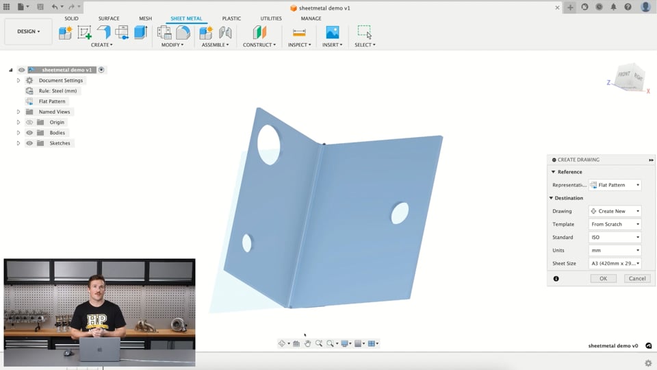
| 08:03 | The alternative is if I save this just as sheet metal demo and click save, I can then create a new drawing from the design and in this drawing I'm going to choose to draw the flat pattern and just create a new drawing of this part and once that opens inside there, then I can create the DXF file from the drawing and in some cases this is a good way to do it, just if you want to visualise exactly what the part looks like when it's flattened before you create the DXF, it gives you a really clear view of what the DXF file will look like. |
| 08:56 | Sorry this is taking a minute. |
| 09:02 | Shouldn't be too much longer, there we go. |
| 09:06 | OK so I can just place this on the part and I'm just going to take off the bend extents. |
| 09:14 | And then I can just delete that there. |
| 09:22 | And the basically from here, we'll just go export, export sheet as a DXF and it's exactly the same process, we just save it to somewhere on our computer and then we can send that to the manufacturer. |
| 09:40 | The alternative is, and this way works best if you're using Fusion 360 for example and you're just using the free version of Fusion 360, Fusion 360 for personal use as it's called, you can't actually export a DXF file from the drawing or from the flat pattern like I just did so a good alternative is to jump back to the original sketch that we made, this one here, oh I'm just going to hide that, and then I can just quickly right click from here and go save as DXF and then I can export that and save that to a location on my computer. |
| 10:22 | Again send it to the manufacturer, say hey could you please cut this part fo me out of 2 mm thick aluminium or whatever grade of aluminium we may want. |
| 10:33 | So that's basically as simple as it is for that. |
| 10:37 | In some cases for a sheet metal part that has bends in it, I like to maybe add a little recess or something into the side of the part to locate the bend, save us measuring it up when it comes back, so we can very clearly see where the bend line is and put it in our sheet metal folder or something like that and bend it up. |
| 11:00 | So I'll just jump back to my notes and we'll move onto the next process. |
| 11:08 | So that is 2D cutting, DXF files covered. |
| 11:12 | The next one we'll talk about is 3D printing. |
| 11:16 | So firstly we'll talk about if we're sending something to a third party manufacturer to 3D print. |
| 11:23 | So this, 3D printing requires a mesh file and basically this is a 3D model that's made up of lots of little points, lines, edges and faces. |
| 11:34 | So that's what a mesh file is. |
| 11:37 | The standard for 3D printing is an STL file. |
| 11:41 | But in saying that, OBJ files, are becoming much more popular because basically you can include the texture or colour in them. |
| 11:51 | So for 3D parts, that require printing in multiple colours, an OBJ file is necessary there. |
| 11:59 | And this is probably going to become much more common and popular moving forward as the technology advances but for now, an STL mesh file is the standard for 3D printing. |
| 12:12 | So if we jump back into Fusion 360. |
| 12:19 | I'll just close that 'cause clearly don't need it. |
| 12:25 | And jump into the data panel here and there was a CRX Jenvey trumpet so very similar to the trumpets on our Jenvey throttle bodies right here. |
| 12:39 | Just cut down a shorter size. |
| 12:43 | But it's just a 3D single body model of a trumpet. |
| 12:51 | So from here we want to convert, save this as a mesh file and this is really simple. |
| 12:58 | Can come to here, file, export, and then find in here, STL file and then export. |
| 13:09 | And that will just go through the process and export that as a mesh STL file onto our desktop. |
| 13:17 | So it's as simple as that really. |
| 13:21 | The alternative is, if we are doing the 3D printing ourself, which is very common. |
| 13:29 | 3D printers are getting much more accessible, cheap and the technology is getting much much better. |
| 13:38 | So 3D printers, we'll quickly cover something called CAM, computer aided manufacturing. |
| 13:46 | So that's basically using the computer to help us with manufacturing. |
| 13:50 | So take our CAD file, our design file and use the computer to create the CNC tool path to be able to produce our design with whatever machine that we're using to create it. |
| 14:06 | So 3D printer in this example. |
| 14:09 | 3D printers use a CAM software referred to as a slicer. |
| 14:16 | So if you're familiar with 3D printing, additive manufacturing, basically builds up layers, prints the layers on top of each other to build up the 3D part. |
| 14:27 | And each one of those layers is essentially a slice, so the slicer creates basically the program to run the 3D printing machine and produce our part. |
| 14:37 | We can do the slicing within Fusion 360 or we can do it within a specific slicing software maybe one that comes with whatever printer we're using or a generic one that then will communicate with different types of printers. |
| 14:56 | So what I'll show quickly now is basically if I wanted to get this part 3D printed or print it myself with the printer that we have at HPA, I could jump into mesh or manage, not manage sorry, utilities, find the make icon here and select 3D print. |
| 15:17 | From here I can select the body, format is STL, binary works fine for this but you can see we have a few other options there. |
| 15:29 | And then I can change things like the refinement of it to maybe make a more refined part for a better surface finish for example and then straight from here, I can choose to send it to the printing utilities. |
| 15:45 | So that's the CAM software or the slicer. |
| 15:48 | In this case we're using an application called UltiMaker Cura. |
| 15:55 | So that's going to send it straight to that if I hit OK, you can see that program opening down the bottom here. |
| 16:05 | And that'll open it and it brings my part straight into there. |
| 16:11 | So from here, just a matter of rotating the part onto the bed however we want to print it, might not necessarily be like this. |
| 16:26 | And basically we're using, this is the printer we're using, Creality CR10S Pro, the material that we're printing it with and then we've got a whole bunch of things in here, this is just the basic, basically our print settings and then we can slice it from here, save it to a harddrive for example and send it to our printer and then basically straight from there, put the file into our printer and click print. |
| 16:57 | And without too much more than that we'll be able to print this part. |
| 17:01 | So that's that process, alternatively, if we come back into Fusion 360 and we jump into the manufacturing workspace, we can do the slicing from here. |
| 17:15 | So we won't jump into this too much today, I'll just give you a really quick demo of roughly how this will work. |
| 17:24 | If we create a new setup, we select the machine that we want to use, I've used it before so it's in here. |
| 17:34 | Select that. |
| 17:37 | You can see it's kind of not quite sitting on the print bed properly. |
| 17:42 | So we can choose. |
| 17:48 | What happened then. |
| 17:53 | Sorry jump back into here, grab that, select, OK. |
| 17:59 | Manufacturing model, click the body, there. |
| 18:03 | And we have the operation type set to additive rather than milling, turning, etc for the 3D printing. |
| 18:12 | So then I can click OK, we're using PLA, that's the filament that we're using, 1.75 mm. |
| 18:22 | Select that. |
| 18:26 | And then from here now I can position it, rotate it 90° onto the bed and you can see it's not quite there so select that component. |
| 18:45 | And that brings it down onto the bed. |
| 18:47 | From there we can click the supports for the model, generate the supports. |
| 18:56 | This will take a while to generate, and then from there it's basically a process of generating the tool path and then we can also choose simulate additive tool path here to basically watch how the 3D printer will print the part. |
| 19:15 | And then after we're all happy with that, we'll just click post process here and it's the same process of just exporting that to a folder on our computer and then basically sending that somehow via a little pen drive or something to our 3D printer and we can then get the printer to print the part. |
| 19:40 | So that's basically all there is to know about 3D printing. |
| 19:46 | You can see here on this model that it's just generated the supports around it so that it can build up the side and do the overhang bit when it gets to that. |
| 19:59 | So I'll just jump back over to my notes. |
| 20:07 | So the last thing we're going to talk about that's common to manufacturing for automotive motorsport applications is CNC machining. |
| 20:18 | So machining, we're talking about milling, lathes, routing. |
| 20:23 | But yeah most commonly we'd say probably milling for CNC machining in a motorsport application and that might be in a three, four, five axis mill. |
| 20:35 | It just depends on what the manufacturer has and what you have access to. |
| 20:42 | So the standard file for this is a STEP file. |
| 20:47 | So this is a 3D solid file of our model but it's not a mesh file, it's just the same as the solid 3D model in Fusion 360 for example but the difference is, I kind of refer to it as a dumb 3D model. |
| 21:09 | So what that means is it doesn't have any of the features or dimensions included in it anymore, it'll all be to scale of course but what it means is we can send the file to the manufacturer and they won't be able to see how we've modelled the part and they won't be able to go in easily and change parameters in it to change the dimensions of the part very easily. |
| 21:31 | They could modify it in their own way if they wanted to but it's a good way of protecting the IP basically for the part so they can't see exactly how you've created it. |
| 21:43 | And basically go through and just remake the part themself very easy. |
| 21:47 | Or if someone else got hold of it. |
| 21:50 | So STEP file is really the standard if you have a 3D model, for example of the intake trumpet from the Jenveys and you want someone to machine that part, you would send them a STEP file of that model. |
| 22:07 | Other CNC processes like CNC tube bending for example, similar thing, you might use a STEP file or an IGES file as another alternative there. |
| 22:20 | But for CNC machining, STEP file is really the standard that's used. |
| 22:27 | So we would generally send this along to a machinist, probably with a technical drawing to go with it as well that will call out things like threads, surface finishes or the material and the grade for example of say aluminium that we want the part to be made out of. |
| 22:45 | So I'll just jump back into Fusion 360, we'll pop back into the design workspace. |
| 22:54 | For our part here, so say I want to get this sent off to a machinist to make this, I could just come here, file, export, and it's the same as always, we just choose the STEP file and I can export that to somewhere on my computer, send that through to them, along with a technical drawing that we've created. |
| 23:18 | And they should be able to make the part. |
| 23:21 | Now the thing is, if you are unsure about what file you need to send to the manufacturer, the easiest thing to do is to is to just ask them and you're best to do this anyway, to ask, hey what file do you need to make my part to the best quality that you can and as efficiently as you can as well. |
| 23:44 | Because maybe they can work with some file but it's not the easiest one for them to work with and it's going to be a real pain for them to work with it and slow it down. |
| 23:53 | That's going to end up costing you a lot more money probably in the long run. |
| 23:56 | So it's best to just go to them and say hey, what do you need if you're not sure. |
| 24:00 | But as you start to work with manufacturers more and more, you'll get a good idea of what they need so you can just flick a DXF file straight through to a laser cutter and say hey, can you cut me this from 2 mm aluminium for example. |
| 24:14 | And also include the quantity, obviously if you want multiple parts cut. |
| 24:21 | But that's the basic process behind it. |
| 24:24 | So at this point, I'm just going to make a call for questions, if you have any questions around this, specifically around the files required for CNC manufacturing, ask them now and I'll just cover a few other details and then I'll come back and answer the questions at the end. |
| 24:44 | So I'll just jump back over to my notes. |
| 24:51 | So far we've been talking about getting third party manufacturers to make our parts for us, other than with 3D printing. |
| 25:01 | And we also discussed CAM, computer aided manufacturing. |
| 25:05 | And this program, if they're integrated into our CAD software like with Fusion 360 for example, or if it's a slicing software for 3D printing, or if it's something else like Mastercam for CNC machining, another program. |
| 25:23 | Basically this takes our CAD model and allows us to create a tool path. |
| 25:28 | Generally speaking, unless we own the machine, we're not going to be doing the CAM work. |
| 25:34 | Of course for something like a very expensive five axis CNC mill, we're not going to be trusted doing the CAM work, nor should we want to or be doing that anyway 'cause the risk of damaging it is going to be very very expensive. |
| 25:52 | So someone doing the CAM work generally is going to have a very very good understanding of the machine and the manufacturing processes involved to make the design. |
| 26:05 | But in saying that, for something like 3D printing, routing, laser cutting if we have a machine ourself, that's all very possible to do. |
| 26:19 | In terms of having a good understanding of the manufacturing process, that brings us along to the next point being DFM which is design for manufacture. |
| 26:28 | So having a good understanding of the process can basically make our design better and more fit for the manufacturing process so the result we get at the end is of better quality. |
| 26:42 | So an example of this would be something like laser or plasma cutting. |
| 26:46 | In some cases if we have a very thick piece of plate of sheet metal that's being plasma cut for example, and we're trying to put a very small hold diameter in it, we're going to get a poor result basically for that hole, it's not going to be a nice round hole. |
| 27:07 | There might be a lot of slag or it might just not make a round hold at all, it might be some other shape. |
| 27:14 | So something around this like design for manufacture there will be like a general rule of thumb that the hole needs to be at least the radius, sorry the diameter of the hole needs to be at least the thickness of the material. |
| 27:28 | And this changes depending on certain machines. |
| 27:33 | And it's always good to talk to the manufacturer about what the requirements are there. |
| 27:37 | Some other things along that line would be the hole not being too close to the edge of the part, common kind of rule of thumb here is not having the hole within about, the radius of the hole distance from the edge so we try to have the hole set inboard at least half the diameter or the radius. |
| 28:00 | Something else would be certain laser cutting machines will not cut above a certain thickness of particular materials so if we're sending something to someone, say hey I want this cut out of 10 mm thick steel, maybe in some cases they just might not be able to do that. |
| 28:20 | On other things with sheet metal, bending is a good example, again general rule of thumb, if you're bending something, the internal radius in it needs to be at least the thickness of the material to avoid cracking or fracturing of the material when it's being bent. |
| 28:41 | It's basically just reducing stress concentrations. |
| 28:45 | 3D printing for example, a good thing to consider is that 3D printed parts in tension, meaning that the forces are trying to pull the part apart, the layers of the part can separate very easily which means that 3D printed parts, if the forces are along a certain axis that's perpendicular to the layers, are very weak, they'll be very strong in compression. |
| 29:17 | So sometimes when we're designing a part, we need to think which direction the forces will be on the part, so when the part is being manufactured, we can orientate it in a certain way so we're lining the layers up with the forces if it's going to be in tension. |
| 29:33 | And then CNC machining can get really really involved, depending on the complexity of the part. |
| 29:42 | But things like, just basically whether the part can be machined or not and if it's a very big part, how efficiently that can be done as well, can significantly change the price of the part just basically on tooling, time alone. |
| 30:02 | So things like fixtures and the tooling, the minimum tool sizes, access to certain parts of the design, there's a lot of things to consider when it comes to that. |
| 30:16 | That's just really an introduction around design for manufacture and in future webinars we're going to try to cover design for manufacture considerations for each specific type of CNC or just manufacturing process in general in a lot more detail. |
| 30:36 | Basically end of the day, hopefully you can work with the manufacturer and develop a good relationship with them so if you send them a part, they will have a good look over it and say hey you need to change this or something so the final result will basically be of high quality and maybe they'll actually be able to make the part. |
| 31:01 | In the worst case you're going to have someone that you send your part to and they just try to make it and basically the result that comes out of the machine is not going to be very good. |
| 31:14 | And then they're going to try to charge you for it and say that it's your fault because you designed it wrong. |
| 31:19 | That's absolute worse case and you obviously want to avoid that. |
| 31:23 | So best thing, contact the manufacturer, say hey what do you need to be able to make the part to the highest quality and as efficiently as possible and then send them that and say this is my design, will you be able to produce it, is there any considerations I need to make here, any changes I need to make to make the part better from a manufacturing perspective and then try to factor those into your design. |
| 31:53 | So yeah from there, that basically wraps it up and we'll just move onto some questions. |
| 32:04 | Evo IX Brend, is a machining course coming? Nothing that I've heard of in the plans there. |
| 32:19 | In terms of fabrication I guess it would be something that could be done around manual machining on lathes and mills for example. |
| 32:30 | CNC stuff probably not but in terms of computer aided manufacturing, we are hoping to eventually do a more advanced CAD course which will dive deeper into computer aided manufacturing so using the manufacturing workspace we were looking at before in Fusion 360 to help us machine our parts, produce them with a 3D printer, things like that. |
| 33:01 | L.A. Thorne The Martian asks, what cnc machine is best for making engine blocks and on average what would one expect to pay for a decent one? That would definitely, I'd assume that would be a five axis CNC mill which is basically, I wouldn't say this for sure but I'm assuming it's probably one of the most expensive CNC machines that you can get. |
| 33:27 | What would one expect to pay for a decent one, a decent CNC machine, I'm assuming rather than a billet engine block. |
| 33:39 | I think, I'm not too sure but maybe there's second hand ones out there for in the tens of thousands of dollars but generally it's up in the hundreds of thousands of dollars and I don't know something like our billet blocks, that company making the billet blocks, I'm assuming they have some CNC machines up in the hundreds of thousands of dollars, if not more. |
| 34:10 | So very very expensive machinery. |
| 34:13 | And that's why the blocks themself are generally in the $5000-$10000 + range cause it's very expensive machines, it's very expensive tooling, it's a lot of, the material itself is very expensive and the expertise as well and just it takes a long long time to machine those blocks. |
| 34:38 | I'm not sure what this name says, Plohl, I won't try to pronounce it. |
| 34:47 | Do you have any suggestions for dealing with sheet metal k-factors? So K factors being the, essentially the stiffness of the material and it's quite, the relation to, this is related to what I was just discussing before about bend radiuses really and I would generally say around that just a good rule of thumb is to use a bend radius at least the thickness of the material. |
| 35:23 | Having done that in every sheet metal part I've designed before, I've never had an issue so if you're bending something that's 5 mm thick, you need to be using a 5 mm thick radius there. |
| 35:39 | Some materials are a lot more susceptible to cracking than others basically. |
| 35:45 | Essentially more brittle and some are more ductile and bend a lot easier. |
| 35:52 | But that is a good basic one to start with of making the bend radius at least the thickness of the material. |
| 36:04 | So that looks like the end of the questions. |
| 36:08 | So I'll wrap it up there, thanks for listening to today's webinar. |
| 36:13 | And yeah hopefully in the future we'll dive into more detail on the DFM considerations for other manufacturing processes. |
| 36:21 | Yeah thanks for watching. |


