327 | Introduction to CAD with ONSHAPE
Summary
ONSHAPE is a browser based CAD package that's popular at a hobbyist and professional level. In this webinar, we'll take a look at how to get setup and start designing with Onshape, take a basic tour of the software and discuss the pro's and con's compared to other offerings.
| 00:00 | - Hey team, Connor here from High Performance Academy and welcome along to this week's webinar. |
| 00:04 | So this week we're going to be giving a bit of an introduction to CAD using OnShape. |
| 00:09 | OnShape is a really popular CAD software package or program at a hobbyist and professional level. |
| 00:16 | So we're going to start off with a bit of an intro to OnShape, a little bit more about what it is and how it compares to some other programs. |
| 00:25 | then we're going to jump into OnShape, I'm going to show you how to get set up and using OnShape and then we're going to jump into OnShape and give a bit of a tour around the software and then model something because I find that's usually the best way of describing how a software works and getting a feel for actually using the software. |
| 00:46 | So OnShape, it is a cloud based software which means that all the files are stored online and it's also browser based so that means that you're using it on your browser, be it Chrome, Safari, anything like that. |
| 01:03 | So what that means is you can access the software from anywhere that you have an internet connection, any device, doesn't really matter, it's not like an application where you download it to your computer and you need to save it on there and use it like that but it does mean that you need an internet connection to use it as well. |
| 01:24 | What it also means is that no matter what operating system you have, be it Mac, or Microsoft, you can use OnShape, it's not, again like an application like Solidworks for example where you must have Microsoft to use it and it won't work on Mac. |
| 01:41 | OnShape will work on Mac perfectly fine 'cause it's browser based. |
| 01:45 | The other thing to know about OnShape is it is developed, the developer in charge of it is PTC. |
| 01:54 | So PTC is responsible for Creo. |
| 01:57 | Creo is a very big CAD software that's been around for quite a lot time and it is arguably on par with something like Solidworks, maybe not as user friendly, not as nice to use but very very powerful software, so that is the same company, PTC, same developer behind OnShape as well. |
| 02:23 | Just a moment. |
| 02:28 | Just having some problems with our streaming software. |
| 02:32 | Anyway moving on, so OnShape itself is arguably not as powerful, well it's, I'll back that up a little bit, OnShape is PTC's offering for a more hobbyist level and it's also based around a file management system being cloud based rather than something like their other offering like Creo which is an application where you have local file storage. |
| 03:03 | So OnShape in that regard is kind of more similar to Fusion 360 in its affordability and its ease of access, although Fusion 360 is of course application based so it's local on your computer, although the file managment is also cloud based. |
| 03:22 | Arguably there's not as many features as Fusion 360 especially when it comes down to something like CAM or computer aided manufacturing and simulation and generative design. |
| 03:35 | Athough those aspects are included in OnShape and OnShape will have 99% of any of the tools you'd need to model anything for an automotive project, in terms of modelling, it's right up there and it's plenty powerful enough to achieve basically anything you want to. |
| 03:55 | A lot of this just comes down to usability and interface, what you prefer and the big differentiators between them being things like being an application or being browser based. |
| 04:06 | Just works for different people so you just need to weigh up what are your priorities when it comes down to deciding between the software. |
| 04:15 | In saying all of that, OnShape compared to Fusion 360 is arguably better for assemblies, so that's working with multiple parts, bringing them together. |
| 04:25 | The user interface is a little bit more focused around that. |
| 04:28 | Not saying in any way that Fusion 360 is bad in that regard, each just have their different strengths and weaknesses. |
| 04:37 | So if we look on my screen at the moment, I just have Googled OnShape and we can click on the website here or we can jump straight into the OnShape free plan right there but we'll go into this here and we'll just click on pricing because that's the next point I want to discuss. |
| 05:00 | So you'll see here there are some different offerings for the product, free, standard, professional and enterprise version. |
| 05:11 | So free, obviously no charge, standard one, $1500 a year and then $2500 for the professional and if you want to go in and look at this for yourself there is some really extensive list here comparing the offerings and what's included in each one. |
| 05:31 | But if we look under the free version, up a little bit here, a lot of this is our modelling stuff here and you can see all the ticks under the free version so it's basically capable of doing everything that we need to do there but when it comes down to things like simulation, for example, and rendering and things like that, that's only included in the professional version so it's quite an expense, albeit a lot less than something like Solidworks, it is a significantly expensive investment to get the professional grade license. |
| 06:10 | The key point here that you'll read under the free version is it says, OnShape standard is available free for non commercial projects where all user data is store in a public workspace. |
| 06:27 | So this may or not be an issue for you, if you're just working on little personal projects and you don't really care who sees your files, not a problem. |
| 06:38 | If you're in a professional environment where you have copyright sensitivity kind of things you don't want people seeing your designs and copying them, that might be a bit of a deal breaker and in which case you'd need to have a paid license but I'll show you a little bit more about that in a moment and it'll make a bit more sense. |
| 07:01 | So we'll just move on from that, if you want to get set up with OnShape it's basically just a matter of clicking here, sign up now, and you can go through that, enter your details, follow through, hit sign up, it'll send you an email and you need to activate it via the email and then you can basically just come back to your server, come to OnShape, hit sign in and you're away. |
| 07:34 | So now that we're signed in to OnShape, give a bit of a tour of the software. |
| 07:40 | So this first area is kind of like the equivalent of our data panel in Fusion 360 and this is just our cloud based file management part of the software. |
| 07:52 | So here, I don't use OnShape personally myself, we're using Fusion 360 mostly so I don't have many files stored here by under this owned by me section, this is where you'd have all your own documents if you had more, I've just got one. |
| 08:12 | If we jump down here to public, we can see that there is, thousands of peoples' files and these are all the public files, shows who they're owned by. |
| 08:30 | So if you're working on a free license, your files will be able to be found in here and the tricky thing is is someone's basically got, has to find it, so they need to know what they're looking for, of course if you name it, if you're working on something like this and you say, you name it a CRX wheel bearing adaptor, that's probably going to be quite easy for someone to find, that might not be a problem. |
| 08:56 | Of course if it's a little bit more sensitive and you want to hide things a bit better, you could name it something completely different. |
| 09:04 | For example, if we typed in here, K20. |
| 09:13 | Hit search. |
| 09:15 | Not sure how well this will work with the speed of the internet, we're having problems at the moment. |
| 09:25 | Some of these things are going to be unrelated to the Honda K20 of course, seems like most of them but regardless you could search in there maybe something a little bit more, oh there we go we've got a K20 valve cover right there so you'd be able to open that up and basically use it as a read only thing and that doesn't mean that if you've saved something in here, someone can go into your document and modify what you've got and basically stuff it up for you, they can copy it to their own library and then work with it from there. |
| 10:02 | But they're not going to mess up your design basically. |
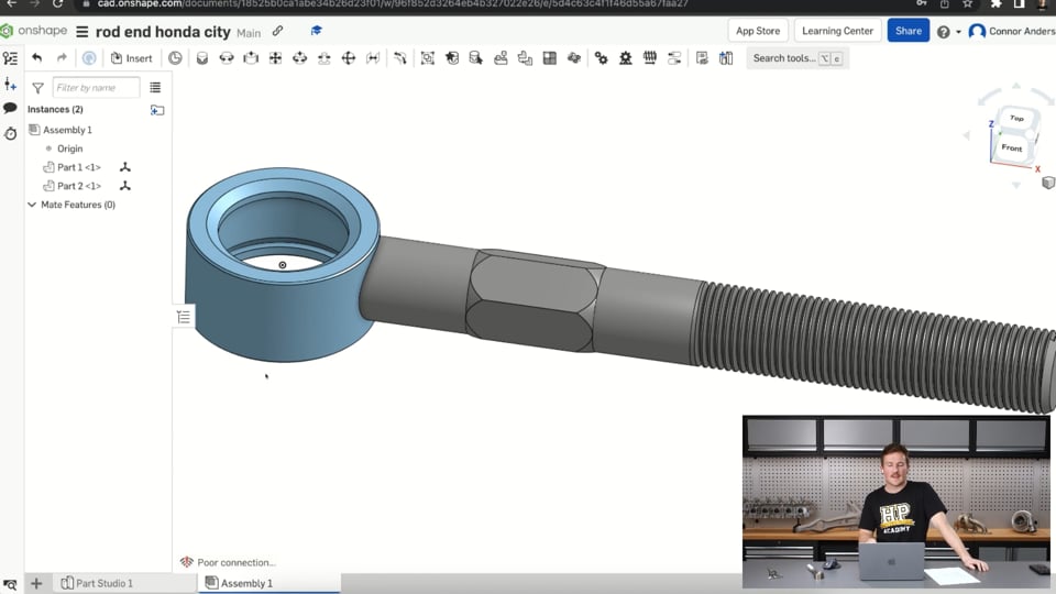
| 10:05 | So anyway moving on, if we jump back to the owned by me section and just open this rod end which I've actually got here and this will be the example, I'll show you how to model towards the end of the webinar. |
| 10:24 | This is basically our model space in OnShape. |
| 10:31 | So it looks very similar to what you'd be used to if you're familiar with CAD, this is 90% I'd say of CAD software looks like this where we have our model space in the middle and we have our toolbar along the top here, we have some sort of browser or feature tree, model tree down the side here that shows the features that we use to create the part, we have a default geometry, that's our top, front and right planes. |
| 11:09 | So fairly standard there and over to the right here we have the views as well so if we click on that we can view from the front, top and basically just use it to rotate our model around. |
| 11:26 | And then the view drop down here, we can jump into there and do things like a section view and cut through that plane and look through, see the section view there, sorry just having more issues with the streaming software, just get that started again. |
| 11:59 | So back along the top of the software here, we also have our sheet metal tools, so if we're working on a sheet metal model, this is where we find, similar to Fusion 360 if you're familiar with that, you can convert things to sheet metal here and use our sheet metal tools here as well. |
| 12:20 | And then down in the bottom right corner here, is our analysis tools. |
| 12:26 | So simple things like the measure tool for example or the analysis tools here, few different ones there and then the mass properties as well. |
| 12:40 | So for example if we jumped over here and selected the parts of the model and we set the, assigned a material for the two parts for example and let's just jump in and choose a stainless steel, we could then pop down here to the mass properties, select both of those and that's showing 712 grams, around about, for that part based on the density of stainless steel which has been assigned to those so the software can calculate that. |
| 13:19 | Moving on down the bottom here we have these different tabs and this is really one of the key differences between OnShape and other software. |
| 13:31 | So a part studio is basically the standard design place so under one document we can basically have multiple tabs and the part studio is where we model the parts. |
| 13:51 | From there after that we can bring them together in an assembly for example, so we can model multiple parts inside the part studio but that doesn't mean they're assembled or anything like that, we can, should just be able to move them around but we bring them together in the assembly and we can specify how they are joined together, use different mate types to have relative motion between the parts and then if you're in a paid version, the simulation side of things is accessible through this assemblies tab as well but if we also added a tab here, this is where we can come in and create a new drawing for example. |
| 14:42 | Or create another part studio but this is all done within that one document. |
| 14:49 | So if I pop back just out to here, this is our one document and I could design multiple parts in here, I could bring them together in an assembly, I could have the drawings all done within here and that's not to say that if I created another document, I could also use those parts in that document as well perfectly fine. |
| 15:08 | So that's probably the biggest difference between something like Fusion 360 and OnShape and if you're familiar with these terms, it is somewhat related to the bottom down or top up modelling approaches that we've discussed in previous webinars. |
| 15:28 | We'll move on. |
| 15:34 | And we'll come back to covering these soon so it'll make a little bit more sense. |
| 15:39 | At this point I'll just make a call for questions, if you have any questions, write them in the chat now and towards the end of the webinar after we've covered the next step, I will do my best to answer them and provide whatever feedback I can. |
| 15:56 | So in the next step we will just model this part and the part that I've got modelled on the screen there but we'll create it from scratch and that should give you a better understanding basically of how the software works and if you're familiar with other software, you'll see the similarities. |
| 16:16 | So this part, if we look under the overhead camera is essentially a rod end. |
| 16:24 | So we've got a spherical bearing on the end here which is encapsulated in this housing, this is all steel and then this is, we've got a threaded shank on it with a bit of hex as well just to I guess be able to grip onto so we can tighten up the lock nuts or whatever on this. |
| 16:45 | And this is going to be used for our Honda City staff racecar of all things, in a lower control arm pick up point to the chassis I think. |
| 16:57 | So basically it's two parts that are welded together, we won't model the spherical bearing itself but we'll model the rest of the rod end and get started here. |
| 17:12 | So if we jump back onto my computer screen and we just go create document and we'll name this rod end Honda City. |
| 17:25 | Owned by me and just hit create. |
| 17:31 | And that will open it straight up and we're just back in our model space now. |
| 17:38 | So we can get started with measuring up this part and modelling it, it's fairly simple, there's nothing too complicated here but it will allow us to use a bunch of different tools. |
| 17:51 | So we'll get straight into it, like most modelling processes, usually starts by sketching something in 2D and then moving to our creation tools to bring that into a 3D model basically. |
| 18:07 | So we'll start here with a sketch on the top plane. |
| 18:11 | Doesn't automatically look normal to the sketch plane so if we just right click and click here, view normal to sketch plane, then we'll just start off by modelling the housing around the encapsulated spherical bearing. |
| 18:29 | So we'll start off with a simple circle based on the origin. |
| 18:37 | And we'll do anther one inside that as well and then if we jump over, where it is, dimension tool, D on the end here, we can dimension this outer one at a diameter of, we're in inches, just a moment. |
| 18:59 | I need to change my workplace units to millimetres. |
| 19:11 | Angles, this should all be fine by now, we could go through that and change everything else but change it to millimetres because that's what I want to work in, sketch again on the top plane and we'll just bang those two circles on there again. |
| 19:28 | Then dimension them, the outer circle we will make whatever the outer diameter of this is. |
| 19:40 | 49.9, 50 mm we'll say, we'll just try to work through this pretty quickly and then the inner can be inside of this, 34. |
| 20:02 | And we'll finish that sketch there, so pretty simple first sketch and then this is our extrude tool, along with the other standard creation tools along the top here, extrude tool has to be the most commonly used CAD tool and we'll just select that outer, the profile between the two circles. |
| 20:23 | So blind, this is basically the extent of our extrude, if you're familiar with CAD but we can leave that as it is. |
| 20:32 | And we'll just make it symmetric so it's going to extrude in both directions from the profile plane. |
| 20:39 | And we will have that extrude the thickness here which is 26mm. |
| 20:50 | And just like that so that's our first 3D body. |
| 20:55 | So moving on from here we will do, I know we can't see the inside of this and I haven't taken the circlip about to pull the bearing out but we've basically got the recess in there for the spherical bearing and then we have a groove for the circlip as well so I'm just going to kind of basically make this up of roughly what I think it'll be. |
| 21:16 | So if we sketch again, doesn't matter what plane, be it the front plane or the right plane, just not on the top plane. |
| 21:26 | Right click again, view normal to sketch plane. |
| 21:30 | And then we're going to use this here which is use project convert, they're all called the same things, similar tools to a lot of other sketch software and we will project this top face so that creates a line across the top there and then project the inside face so that creates a line there, basically where that intersects our sketch plane which is the front plane here. |
| 22:03 | And we'll also create another line down here straight through the middle, I'll just, sorry, view normal to sketch plane again. |
| 22:16 | And then the recess is going to look something like if we call this the bottom here, come up like that, just something simple like that and then we can dimension this, so with most CAD software, when we are sketching, we want to make sure that our sketch is fully defined and what that means is if it's black here, if the lines are black they're shown as fully defined so they can't move, they can't move, that means their location is completely defined, whereas something like this blue line here, I can drag and move that around which is undefined and the issue with leaving things undefined is that they can basically move by accident so we might not notice and we might get to the stage where we think we've finished our project and something has moved a little bit and other things that are referencing that undefined geometry would have moved as well so it's just a way of avoiding errors creeping in. |
| 23:27 | So if I just say the recess here is, we'll say 4mm wide and this distance, we'll put as four as well. |
| 23:40 | And then just to enclose that profile, we'll just link these up here and we'll finish that off. |
| 23:49 | So next we can jump into, actually I'll go back into that, edit that sketch and I'll include the o ring groove as well in there so that'll be, sorry the circlip groove, not the o ring groove, so that'll just be a small little cut out as well and this might seem a little bit arbitrary 'cause I'm setting this sketch up for a revolved feature so sometimes it can be kind of hard to picture what that sketch needs to be but it'll make more sense in just a moment. |
| 24:33 | So those lines are black, that should be defined and then if we jump into our revolve tool here we can hide the part quickly, select those two profiles and then the revolve axis will be this vertical line that we drew straight down the centre of the part. |
| 24:59 | I'll show the main body again and then I will set the, revolve to remove material, so it basically makes a revolved cut. |
| 25:14 | So rather than creating a new body or adding material to the part where that profile is, it's removing material from the solid body that we already have so that's the remove thing there. |
| 25:29 | And we'll just do that, so basically we've got a section here where our spherical bearing could slide down into and we use a circlip to lock the end of it up. |
| 25:39 | So we'll move on. |
| 25:43 | Next here we can see on the top of the part, we have some chamfers around the outside edges which are quite small and then we have a bigger chamfer on the inside here. |
| 25:54 | On the bottom side we also have small chamfers just on both sides of the lead ins there. |
| 26:01 | So we can add those, now very simple and exactly the same process as other software so jump into the chamfer one, we'll set this as an equidistant chamfer, so that just basically means the chamfer on the edge would extend the same amount each side and we will select the edges for the two bottom edges and let's set it at 0.5 which looks about right and the outside one there and select OK so that's just put a little chamfer on those edges and then we'll add a bigger chamfer here and we'll set this as two distances and make that as two and three. |
| 26:56 | So that's just an unequal distant chamfer where one cord is longer than the other. |
| 27:04 | And that is the chamfers added so that's basically the first part really basically drawn. |
| 27:11 | If that was going to be machined before being welded to the shank. |
| 27:16 | So we'll move onto the shank next. |
| 27:19 | And that's going to start with a sketch on the right plane or front plane, again doesn't really matter, we'll do it on the right plane and we will just view normal to the sketch plane again and then sketch a circle centred on the origin. |
| 27:42 | And we will define the radius at whatever this measures out to be, 22 mm. |
| 27:54 | And then from here we can just extrude this. |
| 28:01 | Drag it out to whatever distance we basically need here so that would be the distance from the centre of the part to the end of the shank, my verniers aren't going to measure that but I did model this before so it's actually about 205 mm. |
| 28:22 | And here we're going to choose to create a new part rather than add that because if we selected add it would join it to the original part but since this is two parts that have been welded together, we're going to create two parts and we're going to join them together soon in our assembly. |
| 28:40 | So select that. |
| 28:43 | The issue is here we've got this bit in the middle that we don't want. |
| 28:48 | So if we click the split tool here and then we choose the part we want to split which is this and then the entity to split with which is this outside face of the original part and then we can choose not to keep both sides. |
| 29:07 | So this is going to delete this here, we could flip this to the delete the outside but it's going to, if we flip this back it's going to remove what's inside that there so click that and then now we have one part there and the other part there, just like that. |
| 29:24 | So moving on, what we'll do next is add in the threads for, the external thread on the shank there. |
| 29:35 | And there is an external thread tool here. |
| 29:42 | Just give me a moment to find it, use the search tools, external thread, oh there it is, I was missing it, and we can choose the cylindrical edge of here. |
| 30:02 | And set that as a ISO, M22 is the size, we'll set the pitch as 2 mm I think which is the standard and the length is 95, this is automatically filled it out to what it was because I'd already modelled this. |
| 30:20 | And we choose to split the face here as well. |
| 30:24 | If we select that, you'll see that it doesn't actually model the threads. |
| 30:28 | I'll just jump back into that, I forgot one thing, I'd going to add a chamfer to that lead in edge, it will do that at least. |
| 30:37 | It doesn't actually model the threads but it does split the face. |
| 30:40 | If we wanted to model the threads, the process is a little bit more complicated, I will model them quickly now but it won't necessarily be accurate to what the threads actually would be but I'll show you how to model some threads if something like this happened. |
| 30:59 | So basically we'll start with a sketch on the front plane which is normal to the cylindrical face here and then we'll use the intersection tool and select where the cylindrical face intersects with our profile plane. |
| 31:24 | Then I'm just going to change both of those lines that I created to construction lines. |
| 31:37 | So they won't be included in our profile. |
| 31:41 | I'm just using them to make another part which I'll make now. |
| 31:46 | I'm just going to sketch a small triangle on the edge here which is basically going to be our thread cutting in. |
| 31:56 | So if I dimension this to be, let's say 1.5 by 1.5 and then I can use my constraints. |
| 32:12 | Which are here and I can set these two edges being equal to each other and you can see that that's fully defined the sketch. |
| 32:25 | So from there that is the sketch of the profile that we're going to cut into the face and then we'll use the helix tool which I've lost again. |
| 32:39 | So I'll jump back into here and search for it, helix. |
| 32:46 | And we will select the cylindrical face that the helix is going to be on. |
| 32:52 | Input type we can do as pitch, we'll set the target pitch to 2 mm which was our thread and the start angle, start condition we can set as our start point and select that point on our sketch and clockwise thread, all that's OK and that's just going to basically make a 3D sketch around the outside of that surface that is a helix basically. |
| 33:21 | So we can use this now as a sweep path and cut the thread into the part so if we select the sweep tool here, the sweep tool, like every other CAD program, if we show that sketch again, basically sweeps a profile along a path. |
| 33:42 | So the profile we want to select is our little triangle and the sweep path is the helix. |
| 33:49 | And then we want to use the remove setting here to cut into the part. |
| 33:57 | And then if we select OK that basically cuts our thread into the part and I know that's not accurate to what the thread actually would be but that's just a really quick simple way of showing you how that would be done. |
| 34:10 | So moving on, the only thing left to do is to make this hex piece there. |
| 34:19 | So we'll start with another sketch like normal on the right plane and then we'll view normal to the right plane. |
| 34:29 | And to make a hex we click this circumscribed polygon tool and we place that on the origin and we want to have six sides on it there and then we will just dimension that as 22 to match our diameter of the shank, of the rod end. |
| 34:54 | And cause I put the top point of this in line with the vertical axis there, it's all fully defined. |
| 35:07 | So the only other thing that I want to do here just for this certain part is basically select, change the circumscribed circle to a non construction line. |
| 35:26 | Just like that, because I want to use the profile for something and if it's a construction line, I can't use it as a profile. |
| 35:33 | Finish that sketch up and then I will choose the circular part of the, be easier if I hide this. |
| 35:49 | Choose everything inside there, I'll actually choose that as well and I'm going to view that part again and basically drag this out. |
| 36:06 | So the starting, so I want to make basically a raised cylindrical section, kind of a boss over the top of the part where that hex is, just a circular profile to start with and then I'm going to cut the hex into it. |
| 36:21 | You could just extrude it as a hex section but if you actually look at how this part's been made it was I guess turned up on the lathe at a bigger diameter and then milled to create the hex so I'm just going to match basically what the manufacturing process would be, I'd assume. |
| 36:43 | So for the starting offset, can basically come out here, starting offset off that plane, give it a bit more, call that 50. |
| 36:59 | That's the offset and then the depth, so that's actually how far the extrude goes. |
| 37:05 | I'll call that, about 35. |
| 37:16 | Running a bit slow, and then we can finish that and that's just added that part to the original body. |
| 37:24 | Then I can chamfer those edges, so the top edges and I'll do a two distance chamfer. |
| 37:38 | Where are we up to. |
| 37:42 | Five by two should give us roughly what we want. |
| 37:49 | I've got those numbers the wrong way around, two by five. |
| 38:02 | That's that there, just so that transitions nicely into the face. |
| 38:06 | And then I can jump back into that profile, view the sketch again and then select these outer areas outside the hexagon profile. |
| 38:21 | And I want to cut, so select remove, bring that along, hide that, I want the merge scope just to be of part two so it's only going to cut part two, it's not going to cut that other part that we had here, the original part. |
| 38:41 | And that will work as it is. |
| 38:45 | So view that again and there we have, I can hide that sketch and hide our default planes and that's basically the part there. |
| 39:01 | More or less exactly the same as our sample here. |
| 39:07 | So if we jump into, so, basically this is just the parts created in the part studio and it's not really formed within an assembly or anything like that. |
| 39:20 | So we should be able to drag them, for some reason it's not letting me. |
| 39:26 | If we jump into our assembly now and then we select insert, we can jump into here and from the part studio that's open, select those parts. |
| 39:38 | So we can choose to bring in each individual part or we can bring in the whole design as one thing which is easier, so we'll just select that, click OK. |
| 39:52 | Then those parts, we can set joints between them. |
| 40:00 | So this is the same as assembly in any CAD software. |
| 40:07 | In Fusion 360 they're called joints, in Solidworks they're called mates, in OnShape they're also called mates as well, although this method of doing this is a lot more similar to the Fusion 360 method where we have these mate connectors. |
| 40:27 | In Fusion 360 it would be called a joint origin. |
| 40:31 | So once you get used to it, just a little bit more user friendly way of getting what you want but I find it a little bit more tricky to get exactly what you need in certain situations where it's not so straightforward basically, without overcomplicating that too much. |
| 40:49 | But for example if we wanted to select a revolute mate between the two parts, we could just click joint origin on the parts and that would move them around so those two joint origins are coincided and then we can hit here to play and that will show you basically the relative motion between the two parts that that allows for and then we can actually just go in here and change to different mate types, for example the ball mate type here so if we did have a ball joint sitting in there, we could simulate a ball joint motion as well. |
| 41:33 | We don't want any of that, naturally this is just welded together so it basically just needs a rigid joint beween the two and the easiest way of doing this is selecting the group tool here and selecting these two parts and just clicking OK and that basically just locks those two together so did move that time, I don't know why it wasn't before, it's just lagging a little bit. |
| 41:59 | So you can see now they both move together as a single assembly. |
| 42:05 | If I just undo that a few times to get it back where it was. |
| 42:09 | When you're working in assemblies it's always good to click here and fix a part so it's not all just flying around. |
| 42:19 | If you want certain points constrained, it's good to just ground one of the components. |
| 42:24 | It's called ground in Fusion 360, it's called fix in OnShape, doesn't matter, they both do the same thing. |
| 42:33 | So yeah that basically wraps up a little demonstration of modelling. |
| 42:37 | I know there's a few steps there but hopefully that gave you a good idea of how you'd model something in OnShape and if you're familiar with other CAD programs, you'll likely pick up on some similarities and if you're not familiar with any CAD software, take my word for it, that's basically the same method, the same tools that are used in every software but just the user interface looks a little bit different. |
| 43:06 | So I'll jump into some questions if we have any and try to help out a little bit. |
| 43:17 | Corsa Instruments says, my last experience with Pro/E was with Wildfire (version before Creo). |
| 43:25 | It was fairly cumbersome to convert a 3D model into an engineering 2D drawing. |
| 43:31 | Has that gotten better with OnShape? So I personally haven't really done many technical drawings with OnShape. |
| 43:39 | I know what you mean with Pro/E, I used Pro/E all through university and then in my first job as well for a couple of years out of university and once you get used to it, it's fairly powerful but it's definitely not very user friendly. |
| 43:56 | Has that got better with OnShape? If we had this part here, just jumping back onto my screen, and we just choose to create a new drawing here. |
| 44:11 | Haven't been in here at all yet but let's just look at some templates, A3 ISO template and just open that. |
| 44:23 | See how we get on here. |
| 44:25 | I'd say most of these software now, especially something like OnShape and Fusion 360 that is aimed more at a hobbyist market, that's really what they're focusing on is the user experience so making things as simple as possible for new users. |
| 44:44 | So started a new drawing here and then we can just insert a view, click a view scale here, A3, half scale should fit fine. |
| 45:00 | Insert. |
| 45:03 | Parts studio, OK so it's not the assembly. |
| 45:08 | We can just put that, drop that on, so pretty standard and then projected views up here and to the side and then I assume dimension tools up here somewhere, we can put a diameter dimension on that and maybe the inner one as well and some height dimensions. |
| 45:33 | So in terms of just getting views set up and start dimensioning them seems pretty simple. |
| 45:40 | There's section views on the top, things like that, break views, detail views. |
| 45:48 | It all seems to be there pretty similar to Fusion 360 as well so if that's any reference for you, hopefully that answers your question. |
| 45:58 | It seems pretty simple from a first look. |
| 46:03 | Jump back into some questions if there's anything else, doesn't seem like there is so we'll wrap that up there. |
| 46:10 | Thanks for watching this webinar, next week hopefully we'll be back doing a similar thing with Solidworks for Makers, we're just working through little bugs trying to get that working on the hardware that we have so hopefully we can get that sorted out for you next week and we'll be back to show that so thanks for watching. |


