329 | Introduction to CAD with SOLIDWORKS
Summary
Many consider SOLIDWORKS to be the gold standard for CAD software in the automotive world, but unfortunately for those starting out, it comes with a hefty price tag that can put it out of reach. 3DEXPERIENCE SOLIDWORKS for Makers is a more affordable alternative while still being based on SOLIDWORKS. In this webinar, we'll look at how to get setup and start designing in the software and discuss its pros and cons.
| 00:00 | - Hey team, Connor from High Performance Academy. |
| 00:02 | Welcome to this week's webinar. |
| 00:05 | So this week we're going to be talking about an introduction to CAD or computer aided design using Solidworks and specifically the Solidworks for Makers offering but this is applicable to Solidworks as a total platform. |
| 00:20 | So we're going to talk about what Solidworks is, the few different offerings we have available and how they compare to our other common CAD programs and then we're going to talk about how to get set up with Solidworks so you can start doing your own designs and then from there we're going to take a bit of a tour of the software and then finally move into modelling something which is usually the best way to get an idea for how the software works. |
| 00:50 | So Solidworks to start with is, it's really the gold standard of modelling for mechanical design. |
| 00:59 | A lot of people like to compare any CAD software we're using to Solidworks 'cause it's probably one of the most commonly used ones. |
| 01:08 | Solidworks is made by a developer called Dassault Systems who also make Catia which is another common program, CAD software used for mechanical design. |
| 01:19 | But Solidworks again, it's kind of the gold standard and probably the most commonly used CAD software. |
| 01:27 | Not to say that other software doesn't compete with it, it definitely does, there's a lot of other offerings out there but it's really commonly used so it's a great software to use if you're getting, if you're keen to learn some CAD software then it's a really good one to start with or move into 'cause it's used in a lot of professional environments as well so it's a good one to learn if you're looking to move into the motorsport industry or in mechanical design, it's a really commonly used software. |
| 02:01 | So what we'll be talking about more so today is Solidworks Connected. |
| 02:08 | So this is just the same, or 95% the same as the standard Solidworks desktop application that has been used for a long long time but more recently Solidworks Connected has become a thing and basically what it is is it's the same application, it just interfaces with the new 3D Experience platform from Dassault Systems and basically that is just a system that's been set up to allow for a cloud based storage of the CAD files, anything that we're working on and allow for collaboration basically between team members, yeah just cloud based storage of stuff. |
| 02:52 | So if you are in a professional environment, previously it would be very common to use a file management system native to Solidworks called PDM. |
| 03:03 | And this 3D Experience is really just a bit of a development on that and become a completely cloud based system. |
| 03:13 | And that's not to say that with what we're talking about, you can't save files on your computer, on premise as well, that is definitely still an option. |
| 03:22 | So if we just jump onto my computer screen, we'll jump now into, this is the 3D Experience platform, this is my dashboard here and we just have a welcome screen here and we have also contents, so this is basically things that I have access to or I've created, here's the common space down here with some CAD files. |
| 03:51 | Tasks, this is something that if you're working in a team in a professional environment you might be using, something like someone has assigned you a task to pair review their drawing or something, that would probably be in here and then there's communities as well but this is our 3D Experience dashboard. |
| 04:12 | So basically we could share our design files and we'd be able to access them from any location and there's some other browser based software in here where we could access our design files if we're out on site or at a racetrack for example and we want to bring up a design file and have a look at it, we could do that on our phone or on a tablet or anything from here. |
| 04:43 | For example if we just look at my screen again, that's something like X Design or X Shape, that's just a browser based software but Solidworks itself is actually still an, even Solidworks Connected is still an application based program that we have on our computer. |
| 05:08 | One thing I wanted to note here as well is this being an application is only available on Microsoft Operating Systems. |
| 05:21 | It isn't available on Mac. |
| 05:23 | I usually work day to day on a Mac laptop but if I'm using Solidworks I need to be on a Microsoft platform. |
| 05:31 | The alternative to that is if you use a virtual operating system, something like Parallels or Boot Camp, on a Mac you would be able to run Solidworks on that through your Microsoft virtual operating system. |
| 05:48 | But there's some other complicatons with that and considerations around basically just the speed that you'd be able to run it at. |
| 05:55 | So if you just jump back onto my computer and onto this page here, this is the Solidworks for Makers offering, so 3D Experience Solidworks for Makers. |
| 06:14 | What's important to note here is it's commonly misunderstood that Solidworks for makers is its own application, it's own version of Solidworks. |
| 06:25 | But if we actually look at what is included in this description here, we have Solidworks Professional. |
| 06:32 | So, sorry just a moment. |
| 06:41 | We have Solidworks Professional through the 3D Experience system and that is just the full Solidworks application at the professional grade so Solidworks usually has three tiers, they have the standard license, professional license and the premium license I think it's called and they just have some different abilities in terms of tools. |
| 07:05 | So the Solidworks for Makers offering includes Solidworks Professional and a few other things as well and you can see the price of it here, it's about $8 USD per month if you want to pay monthly or a yearly subscription is only about $80 USD. |
| 07:22 | So really really affordable and that's basically for the entire Solidworks application as you'll see in a mmoment. |
| 07:31 | So this is the offering that we're using today. |
| 07:33 | And the most affordable option to get Solidworks, otherwise it's Solidworks desktop application for years has been about $4000 USD to get started and then you pay an annual maintenance fee which I think is over $1000 as well so a very expensive program but this is a really good alternative to that that is a lot more affordable. |
| 08:03 | So if we just jump onto my computer screen, I'll give you a rough idea of how you would get set up. |
| 08:11 | So you could basically jump here on this page so if you just Google Solidworks for Makers this will be the first one that pops up and then you would just click buy now and then you can move from here and it will prompt you to create a 3D Experience ID. |
| 08:33 | I'm already logged in so it's going to sign straight into my thing, oh no you can work through here so go to payment, it'll basically ask you from here to create a 3D Experience ID and then you can move through and complete your purchase. |
| 08:50 | And once that is done, I'll just jump over to another window I have here, you'll be able to sign into your 3D Experience dashboard. |
| 09:00 | In here, once you have purchased Solidworks, you'll have access to it and you can jump up into the top left hand corner here to the roles, apps and solutions portfolio and this is where you'll have your roles and a lot of other things as well but if you jump here to 3D Experience Solidworks Professional, you can download Solidworks Connected from here. |
| 09:31 | Click that and it will eventually download and then you can install that on your computer. |
| 09:36 | And then from there, you'll be able to come back into this dashboard and launch Solidworks Connected from there. |
| 09:46 | I already have it open so it's not a problem but once you open it for the first time you can also create a shortcut to the application from your desktop so it makes opening it up a lot easier. |
| 10:01 | So if we jump into Solidworks Connected, we have Solidworks Maker here as the offering but this is going to look a lot like, I'll just close this, our Solidworks for anyone who's familiar with it. |
| 10:20 | So this is just our kind of opening screen and we'll just jump up here and go new and we'll create a new part. |
| 10:33 | Open that up. |
| 10:35 | So once we're in here we have basically what looks like any other standard CAD software or CAD program. |
| 10:47 | In the middle here we have our model space, if I just turn on the planes, we have our front, top and right plane and this is very standard for most CAD software model spaces. |
| 11:05 | From there we have, up the top we have our tabs here such as features, sketch, mark up, evaluate, we'll come back to these in a moment. |
| 11:18 | And then we have our tools in here as well and if we just right click kind of up the top here we can jump in and we can add tabs that are hidden, so things like sheet metal for example, mesh modelling tools which we'd be using for 3D scanning and want to say there's, yeah surfaces here as well. |
| 11:40 | So they're some commonly used tool sets as well and also if we right click and go to toolbars for example we could attach our sketch toolbar and that just attaches some sketch tools along the side here but we don't really need that 'cause a lot of this is going to be up in our tabs along the top here. |
| 12:01 | So just back to our tabs, so we have features here which is really where our commonly used 3D solid modelling tools are, we've got for example, extrude and revolve and there's sweep, loft, extruded cut hole wizard, a bunch of other stuff here, filets, pattern tools, draught and then we have our datums here as well to create reference planes and axes, coordinate systems, points. |
| 12:33 | Moving along a tab, we have our sketch tools, then as we added before, we have our surface modelling tools, sheet metal tools, so that's for modelling with sheet metal specific manufacturing methods. |
| 12:46 | Just being able to create sheet metal parts using bends and forms and all sorts of different stuff like that. |
| 12:54 | And then a mesh modelling toolset, you see everything is kind of faded out here because I have nothing in my model space yet to be able to use a lot of these tools but this is the type of stuff we'd be using if we were planning on working with a 3D scan which is a mesh model. |
| 13:14 | Or potentially moving to using a 3D printer which uses a mesh model as well, that would all be in there. |
| 13:26 | And then our evaluate tab is where we can do things like measure parts of the design, there's some mass properties here as well which you can select when you have 3D bodies and then there's some other stuff like interference, detection and other things like curvature analysis and that is all under our evaluate tab. |
| 13:48 | Now if we just jump along here to the Solidworks add in tab we can see here, there is some simulation stuff and motion analysis that is basically add in, so something that you would pay extra to have access to and that's all included under here, scan to 3D again is something that allows you to use, work with 3D scans a little bit more effectively, developing 3D models from your scans. |
| 14:24 | So that's all under the Solidworks add ins. |
| 14:28 | So just moving on here down the left hand side we have what's called our design tree. |
| 14:33 | We can see our origin planes here and our origin point and when we start creating a model we'll be able to see down here our features as well in a bit of a timeline, as we create them they'll jot down here but you'll see that in just a moment. |
| 14:51 | Over a the top of our model space we have our view tools so just different things here about how you want to view your part, how you want it to look in your model space and yeah we'll move on from that. |
| 15:07 | Up the top here, if we click this little arrow, just hover over it, we have our file edit view, all the normal stuff here so you can see here that you can save your design to the 3D Experience common space, so cloud based storage and then this here says save to this PC so that's on premise storage as well. |
| 15:30 | And this is where you'd create a technical drawing from your part as well and there's a lot of other view options and just all your normal stuff through there. |
| 15:39 | So if we move on from that, over to our right we have the 3D Experirence tab here. |
| 15:45 | So in here we can just see a bit of a common space where you might have parts and be able to access our cloud based storage from this tab to the side so that's really what Solidworks Connected is all about, just being able to work with that 3D Experience platform. |
| 16:05 | So from there we'll move onto modelling something. |
| 16:10 | Just to give you a better idea about how the modelling process works. |
| 16:15 | So if we just jump under the overhead, onto the overhead camera here. |
| 16:20 | What we have here is a brake disc hat from a floating rotor setup. |
| 16:28 | This is I think the old one off our SR86 endurance racecar and I'll just grab this brake disc over here for anyone who's not familiar with these, this is not the right disc to go with this hat so the diameter's not going to be right but basically we have our iron disc rotor there and the we have our hat which would bolt onto these holes if it lined up, just decoupling the two and then obviously we have our wheel studs through the middle here to secure the brake disc to the hub. |
| 17:21 | What we'll do is we'll create a quick model of this part, this is a really common part that you'd model and maybe change the outer diameter here for different sized discs with different annulus and also change the offset between the mounting face here or here and basically that there so if you look from the top, basically the distance here is a common thing that you'd change, depending on your vehicle and what brake caliper setup you're running to centre the caliper over the brakes. |
| 18:00 | So we'll move on and we'll create a model of this part in Solidworks. |
| 18:05 | So what we're going to start with, is this is a nice, there's a circular part that is basically a revolution about this centre axis that runs down the centre of the part here so this makes it perfect for using our revolve tool to model this. |
| 18:27 | And if we're going to do that and use the revolve tool, we want to basically, if we for example use this ruler, was taking a plane, a section cut straight through the part here and we're looking at the cross section, we want to basically create a sketch of that cross section so we can revolve that around the part to build the 3D body. |
| 18:49 | So that's what we're going to do, we're going to start on Solidworks here and click the, there's two ways to do this. |
| 18:59 | You could create a sketch from here on one of these planes and then select the revolve tool to rotate that about a centre axis there or we can just straight away select the revolve tool. |
| 19:14 | And it doesn't so much matter what plane we're going to sketch on but we'll choose the front plane and you can see that our revolve tool brings us straight into creating a sketch to use as the revolve. |
| 19:27 | So it can take a little bit of imagination here to kind of make a cross section here and understand what that's going to look like. |
| 19:38 | So we'll start sketching and you'll be able to get a bit more of an idea about what it is. |
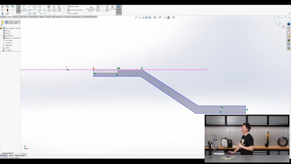
| 19:45 | So the sketch is going to look a little bit like, I'm just going to hide these planes to make it a bit easier to see. |
| 19:53 | Oh delete that, jump back to our line tool, sketch is going to look a little bit like this. |
| 20:08 | And you can see that that nicely snapped to all the different points as I was moving through. |
| 20:15 | So that is kind of like roughly what the cross section is going to look like and we only need to do one side of it, we don't need to sketch the same thing over here, we can just do one side and then we'll be able to revolve this profile 360° about this central axis to create the part. |
| 20:34 | So in saying that, when we dimension these parts we've got to remember that we're dimensioning half of the radius, we're dimensioning the radius not the diameter. |
| 20:46 | So this will make a little bit more sense in a moment. |
| 20:49 | So we can see here that it's nicely snapped to a lot of these things so this line here is already running horizontal with our origin point. |
| 21:01 | As I sketched it, these lines are vertical, that's what these little green things are, our relations. |
| 21:08 | So this is our constraints in Fusion 360 if you're familiar with that, that's those there so saying that this line here is vertical, this one's horizontal, these are horizontal, vertical and these are just coincident points and if we hover over them we get a little description of what they are and where the corresponding one is. |
| 21:30 | So we'll move on anyway. |
| 21:33 | If we start with the dimension tool and select this line here and we dimension that to here. |
| 21:39 | And then we can set this dimension, so if we look back at the overhead camera we can measure that centre bore and that is 58 mm. |
| 21:55 | Yep 58 and the trick here is just dividing that by two so we can do that maths in the dimension, 58 divided by two and that gives us 29 and then as we go we can kind of just... |
| 22:08 | Exit out of the tool, just drag things around a bit so we kind of keep our shape, it's a bit easier to understand. |
| 22:18 | This next one here is going to be the thickness of the main face over the hub. |
| 22:27 | So if I just measure that, it's 8 mm thick and we're just doing this roughly, not to the exact dimensions. |
| 22:37 | Just to get an idea about how it all works. |
| 22:41 | So this, we'll change this a little bit and we'll dimension from here which is the outer edge of that top mounting face to the centre and if I just measure that with the ruler, we're at about roughly 150 mm so same thing here, 150 divided by two and that's that top face. |
| 23:05 | The outer diameter we can do next so this here measures at 260 mm across. |
| 23:22 | Yep 260, same thing, 260 divided by two, we can measure the thickness of this outer edge here, at the thickest point it's 9 mm. |
| 23:39 | So next we can measure the offset, so the distance between this face and the top mounting face and this is easy to do with our verniers here. |
| 23:53 | Measure there and we get an offset of 21 mm. |
| 24:03 | Then from there, next we can just take a measurement from here. |
| 24:13 | And that's just this outer face, do this quickly, add about, we'll call it 23 mm. |
| 24:24 | Then we can just set the distance between these two, oh so that's a good example here, so these ones aren't currently running parallel so it's giving us an angle dimension between the two so if we just delete that and jump into here and go add relation we can add a relationship between these two lines and we can basically just have them running parallel and then when we jump back in and add, oh sorry, a dimension between them, we could just set that to eight as well. |
| 25:06 | And leave that there. |
| 25:12 | So that is our revolve and I forgot to add a vertical axis so if I just finish that and jump back into here I'll look at that front plane again. |
| 25:31 | And I'm just going to make a little vertical line that's going to be our revolve axis. |
| 25:36 | So we're going to end sketch here, can choose the profile to revolve about and then the axis, that's wrong, it's this one here and just going to take that off thin feature and you can kind of see what it's done there, if we changed that to 180°. |
| 26:05 | It's not going to show us, yep there we go, it would just do 180 degree sweep of that section basically, about that central axis. |
| 26:14 | So we'll just change that back to 360 to get the entire part and then finish that and there we have that. |
| 26:24 | I'll try really quickly to change... |
| 26:32 | ...the look of this if I can, maybe bronze, see how that looks, OK sure. |
| 26:40 | That'll do for now. |
| 26:42 | So that is the outer body of our part made and we're just going to now add in all the features and make it look a bit closer. |
| 26:50 | We'll start here by using the fillet tool which just rounds our sharp edges and we'll select these sharp edges here on the top and bottom of the part and we're just going to put a 10 mm radius on those and there. |
| 27:10 | So these lines we can see here are just the tangent edges but you can see that that's nicely rounded. |
| 27:18 | So we'll move on and next I wnt to add another little part here, so there's the little chamfered edge around the bottom here so same place as our fillet tool, select chamfer and then we can just select this bottom edge here and we can add a 5mm chamfer to that, select OK, just like that. |
| 27:45 | Moving on we will extrude, oh I actually don't want to do an extrude, I wanted to do an extruded cut to cut the five wheel stud holes in the top, through the top section. |
| 28:06 | So I choose that top face to sketch on, I can create one circle and then another one which will be our pitch circle diameter and then I can change this one here to construction mode so it's not going to be included in our final profile. |
| 28:27 | This hole, oh didn't mean to do that. |
| 28:33 | Just go back. |
| 28:36 | This hole here, I want to dimension it, click the right tool first. |
| 28:45 | There we go sorry. |
| 28:48 | So these holes are 12.5, obviously if we were modelling this for an actual part to be used, we'd take a lot more care, and then these are on a 5x100 PCD and then the last thing we're going to do, so you'll notice that this is blue which means its position isn't constrained, essentially meaning it can be rotated and moved. |
| 29:16 | If I want to fully define its position, I can add another relation here between that and set that as vertical so that hole now goes black, showing it's fully defined, I can no longer move it, that's just good practice with CAD modelling so you don't end up with something moving by mistake and you wonder why your part doesn't fit properly in the end because something moved while you were modelling it. |
| 29:44 | It's just good practice to keep everything locked down to avoid those unintentional errors creeping in. |
| 29:51 | From here we can jump over to our circular sketch pattern tool, this is perfect for PCDs. |
| 29:59 | And we can click that there and then we've got our 5x100 PCD so we just change quantity there to 5 and that's our PCD there and we can exit the sketch and that's just going to create an extruded cut of that and we can do that through up until next which is the next face from it and finish that and that is our PCD cut into the top face. |
| 30:30 | Moving on, we're going to use a similar approach using a pattern to pattern all these cut outs around here for attaching it to our disc and also the pockets here as well which are just cut into the side here to reduce the thickness, probably save a bit of weight. |
| 30:51 | So we're going to use the same kind of method and we're going to just create one of each and then we're going to use the pattern tool, circular pattern tool to copy those parts all around the whole part. |
| 31:07 | So again if we create, we're going to do this time using a sketch on this outer surface. |
| 31:18 | And first of all we're going to convert entities so we're just going to use that tool and we're going to click this outer edge here and basically that just brings that onto our sketch, so it includes that outer diameter circle onto our sketch and then just create a simple sketch of the cut out for the box first, just roughly, just avoiding some snap points there. |
| 31:48 | Add some relations, I want this line and that line, oh no sorry can't do it like that. |
| 31:55 | Clicked the wrong tool anyway, add relation, so this one... |
| 32:07 | ...is going to be vertical, that one's already vertical and this is perpendicular here so you know it's horizontal. |
| 32:14 | And we're going to add a point here to the mid point on that line and if I make that mid point, in vertical alignment with our origin point, then that means that whatever spacing this is spaced equally about that central plane. |
| 32:44 | So the spacing of these two here, we can measure that and that is 10mm. |
| 32:54 | And then the depth of that, oh that's not good. |
| 33:06 | We can set that as well, measure that quickly at, verniers. |
| 33:21 | About 17. |
| 33:28 | So we can, that's our, we'll add to this with the fillet tool quickly here. |
| 33:36 | So were going to fillet, make a little 2mm radius between these edges, it's just giving me a warning here because that point is in the centre of that line and we're changing that line but yeah we've just added a radius to those sharp corners at the bottom just to match our part. |
| 34:02 | Then moving on we can create, in the same sketch these little pockets here so we're going to do this slightly differently, select the outer edge here and we can see that this yellow dotted line coming through the middle of the part, goes straight to the origin point. |
| 34:23 | So we're going to line up with that, just so it's a radial line. |
| 34:29 | We'll come out to this, I'm actually going to convert that middle edge as well. |
| 34:38 | To include that in the sketch, and then we just have another line from here following, hopefully to the centre. |
| 34:53 | There like that. |
| 34:56 | So next we just need to dimension this, we'll just do this really basically. |
| 35:09 | Make that eight. |
| 35:12 | Distance between these. |
| 35:31 | The length of this little line can be, doesn't particularly matter for this, it's just a demonstration but you get the idea. |
| 35:43 | Then from this, no we'll go this point to this point and that should fully define it. |
| 35:55 | And that will be 25. |
| 36:04 | And we can exit the sketch there so next we're going to jump back to our features and we're going to do an extruded cut. |
| 36:15 | Not like that though, extruded cut, we're going to select that sketch that we just did and we're going to cut that through up until next works great there again and we're going to cut that hole for the bolt straight through the part and then another extruded cut we can expand that in our timeline or browser here, click that sketch again and use this profile here and rather than going through the whole thing, we'll do that as blind and set that just as 3mm which I'll just check. |
| 37:00 | Yep 3mm there. |
| 37:06 | So that's made that and then we're just going to copy the little radiuses in here with the fillet tool this time so if I just select those edges that I want to apply, not the face, the edges, that I want to apply the radius to. |
| 37:30 | And I'm going to set that radius to the same as the depth of the pocket which is three, there, just like that. |
| 37:40 | So now we have one instance of each of those features and we can simply jump over here and use the circular pattern tool and select from our timeline, each of those features, including the fillet and then we can copy that about our central axis. |
| 38:11 | Which I need to create first, sorry we'll come back to that. |
| 38:16 | So I'm going to first create an axis for the revolution around here and then jump back into that circular pattern tool, select the features that I want to pattern and then the axis there is selected already and you can already see 10 as I've modelled this before, is the right number but let's say we had four, it would just do it four times but there's 10 instances on this part so we'll do that. |
| 38:48 | And then there we have it, that is basically our part modelled completely, the same as the part we had here, with all those features on it as well. |
| 39:01 | So from there we're basically finished with our... |
| 39:06 | Oh just at the moment I'll just make a quick call for questions, if anyone has any questions and wants to drop them below in the chat I'll do my best to answer them in a moment but before we get to that, so we've got our part here and if we wanted to work from this for example we can save here to 3D Experience or save to our PC or from here we can create a drawing from the part as well, maybe we want to make an assembly from the part, it's also possible to come here, create a new assembly and then we can insert components, that part's not saved, I'll do that first. |
| 39:53 | So if I save this part, sorry, blown it. |
| 40:03 | Redo that. |
| 40:08 | And save to 3D Experience. |
| 40:13 | Call it part one. |
| 40:23 | Right unable to save, I'm not sure what's going on there but basically we'd be able to insert the component straight into this here and then we can work from there with our assembly processes and create mates. |
| 40:37 | We will cover that more in a future webinar, this was really just an introduction to using Solidworks and basically how you go about modelling in it. |
| 40:47 | Hopefully you'll see that it is very similar to a lot of other CAD software, other CAD programs out there. |
| 40:53 | There's advantages and disadvantages to both but once you understand how to use one, they're all very relatable. |
| 41:01 | So that's just an introductory look and in the future we're going to dive more into how to do more technical kind of tasks with them like working with 3D scans or working with an assembly for example and maybe some simulation as well in the future. |
| 41:15 | So I'll just jump into my notes and we'll have a quick look at if there's any questions. |
| 41:34 | Chris Clifton, since you are fabricating, why not just raise the steering rack like in Audi A4s? I'm not familiar with Audi A4s, I'll have to go have a look, maybe that will work great for us. |
| 41:48 | I know what we're looking at is trying to maintain the factory uprights, the factory upper wishbone, upper A arm and just really create a new lower wishbone and castor arm so we're trying to maintain a lot of the factory supension as possible and that makes it a little bit tricky with the steering knuckle. |
| 42:10 | If we were changing the upright and using a different steering knuckle, it's very easy to move, well it's not very easy but it's possible that we'd be able to move the steering rack up a lot higher but that's kind of the main issue we're having at the moment but we'll definitely have a look at the Audi A4 example that you talked about and see what that looks like. |
| 42:31 | Yeah we're open to ideas at this point. |
| 42:37 | Matthew Mairs, do you think I could use OnShape for the CAD modelling course? So we get this question a lot and I showed OnShape in a webinar the other week and in the future I think we'll definitely be adding some worked examples with OnShape as well. |
| 42:54 | In saying that, in our CAD modelling course we are using Fusion 360 for a lot of the process through the course, all of the examples and screen shares are working within Fusion 360 and that's not to say that you can't take this course and apply it to any other CAD software, other CAD program, you definitely can. |
| 43:19 | For example when I did the webinar two weeks ago on OnShape I started using OnShape the day before, it's very easy to figure out how they are and they are all very similar. |
| 43:32 | Fusion 360 has a free license so I really don't see why you wouldn't just start using that free license, get set up with that free license, have Fusion 360, follow the course through using your free license of Fusion 360, learn what you need to know and then from there you can jump into OnShape, Solidworks, any other CAD program and use it perfectly fine. |
| 44:00 | It will make it a lot easier to follow along with the course using Fusion 360. |
| 44:07 | In saying that, if for some reason you only wanted to ever use OnShape, then yeah you could follow along with the course on OnShape, you'd just have to know that where each of the, every single difference between the program is basically so if I'm sketching on a plane and then extruding something in Fusion 360, that is going to look very similar in OnShape but it's just going to be enough difference that you might as well just do the worked examples with Fusion 360 and then transfer from there. |
| 44:42 | Because there is that free version of Fusion 360 to use, yeah I'm not really sure why you wouldn't but open to be proved wrong of course. |
| 44:54 | And that looks like the end of our questions. |
| 44:57 | So thanks for listening along to this week's webinar, as I said that's just an introductory look at using Solidworks for CAD on a automotive or motorsport grade part. |
| 45:07 | In the future we're going to be diving into more detail. |
| 45:10 | At the moment we've looked at Fusion 360, OnShape and now Solidworks. |
| 45:16 | If there's any CAD programs that you'd like us to dive into more, we'd definitely be open to doing that so flick us through a message. |
| 45:24 | And in the future we'll dive into some more advanced topics as well. |
| 45:29 | So thanks for listening to this week's webinar and we'll see you next week. |


