331 | Stop Wasting Time Measuring Parts - Use Canvases Instead
Summary
Ever tried to model an existing part with an irregular shape? It's easy to get frustrated with the amount of time you might spend measuring. In this webinar we'll cover how to use 2D images (aka canvases) as references to design around.
| 00:00 | - Hey team, Connor from HPA here and welcome to this week's webinar. |
| 00:04 | So this week we're on another CAD topic and this week we're going to be talking about using 2D images or photos, also known as canvases in CAD, basically to help us with our designs and be able to use as a reference to design around, to speed up the process really. |
| 00:22 | So we're going to be covering how they're useful, specifically for design of motorsport parts as well as some considerations and tips and tricks around using them and then also how to basically get set up in CAD and use them. |
| 00:39 | For this example we're going to be using Fusion 360 but the process and the ideas is very similar no matter what CAD program that you're using. |
| 00:49 | So we'll just start with a bit of a rundown on canvases or 2D images and why we might use them in CAD. |
| 00:58 | So 2D images, there's a few different ways that we can use them or a few different forms that they can come in. |
| 01:07 | So this could be a photo taken with our phone or a camera, it could be a technical drawing specifically something like an isometric projection drawing or it could be something like a 2D scan from a flat bed scanner as we usually have with our office scanners and printers. |
| 01:29 | But we'll get into each of those in more detail in an example as we progress further. |
| 01:35 | So in terms of examples of where these might be useful for motorsport. |
| 01:40 | If we have something like a bracket or a mounting surface with bolt holes, something that is an irregular shape, that's where we might use a photo of that surface or a scan or a drawing and bring that into our CAD program to help us design around. |
| 02:04 | We also might use it for modelling components that already exist like a brake caliper for example which I'll show you something related to that in a moment. |
| 02:17 | Or also the flange of a cylinder head which the valve cover would mount to and that's actually the process I used when modelling the billet valve cover for the SR20 VET in our GT86 racecar. |
| 02:33 | So the reason that we would use them is for a reference to model around and this is going to go a long way in saving us time measuring the parts, if you can imagine you have a part that you want to recreate in CAD then you ned to take a lot of measurements of it. |
| 02:52 | For some parts this might be really easy, for other parts this might be, take a long time and for other parts it might be almost impossible if they are a really irregular shape. |
| 03:02 | So it saves a lot of time there and we can follow those irregular shapes basically the same as a tracing method if you had an existing drawing for example and as a kid you held it up against the window with a sheet over top of it to get the light come through and you trace it, it's kind of the same idea that we're using here, it just allows us to copy it more quickly and saves us a lot of time in the measuring process. |
| 03:32 | So let's talk about some considerations to get the best results from our canvases or our 2D images. |
| 03:40 | Obviously the image is going to have to have the detail and the quality that we want so when we bring it into CAD, we can copy the profiles easily and see them and they are also to the correct size. |
| 04:01 | So if we bring something into CAD and we're working in a parametric modelling system that is to scale which is obviously what we want to be using for motorsport design, design of any engineering components really, we need it to be to the correct scale. |
| 04:19 | There's no point modelling around it if it is a very small size in CAD and then going to make the part and finding out that it completely won't fit because the scale is wrong. |
| 04:33 | The other thing to consider, and this is a little bit more important, well equally as important, maybe a little bit more overlooked, is that the proportions of the image are correct. |
| 04:44 | So by that I mean probably one of the key areas this happens is from perspective distortion. |
| 04:52 | So with 2D images, it's very easy to get this and this is mostly related to the way that cameras work but we'll get into that a little bit more in a moment. |
| 05:06 | So I'll just open a thing here and I'll try to explain this a little bit more, so I've got a roll centre adaptor here, hopefully this will open up quickly. |
| 05:19 | So perspective distortion is something we get in our human eye or in the camera from lenses and it's basically the distortion just due to optical waves bending around things really. |
| 05:33 | So if I go here and I change from the orthographic view here we have the orthographic projection on the screen at the moment and I'll just change to a perspective projection here and you should be able to see how the part has changed. |
| 05:53 | So basically we have, as the parallel lines here go backwards they will meet eventually in a vanishing point and when we are taking a photo, this is the type of effect that we will get and we're trying to basically lessen that degree which we're going to talk about a little bit more in a moment but ideally we would be using an orthographic projection as an image there so we get the true shape of something when we bring it into CAD and when we copy it, there's no distortion. |
| 06:33 | So if I just jump over to a photo I have here, this gives a pretty good idea of what we're talking about, and as I mentioned, just the way cameras work, we're always going, camera lenses work, we're always going to get some distortion and we just want to minimise it. |
| 06:55 | So two key ways of minimising it when we're using a camera and one of them is to use the longest focal length we can so think of a lens, the more zoomed in it is, the longer the focal length and this will minimise the perspective distortion. |
| 07:13 | So ideally we'd be using about an 85 mm lens or above, we can probably get away with as small as about a 50 mm lense but anything lower than that, the effects of the distortion are going to be significant enough where it could make the image unusable. |
| 07:37 | It just depends case by case on the part that we're designing around. |
| 07:42 | If we just look under the overhead camera at my phone for a moment, this is a common thing, iPhones now have three lenses or some of them do. |
| 07:53 | And when we jump into the camera, just a moment. |
| 08:06 | There we go, when we jump into the camera we have the three options around the bottom of 0.5x zoom, 1x zoom and 2 as well. |
| 08:16 | And for example if we're using this camera, we want to be on the 2x one and that is about the equivalent of a 77 mm lens focal length. |
| 08:27 | So that's what we'd want to be using in that case if we used, for example the 0.5 one, we have a lot more perspective distortion and if we zoom in more, we just move a bit further away and the image becomes a more true shape. |
| 08:44 | So that's something to consider if you're taking a photo using an iPhone or any phone for that matter but if you're using a camera the further away you can be from the object, and the more zoomed in on it you can be, the more you'll be able to minimise that so that's another thing to consider, being further away from the object is better for distortion. |
| 09:10 | And the last thing to consider is that you just want to be straight onto the object. |
| 09:14 | So if you were trying to copy the outline of a mouse, again just looking at the overhead camera, if you took the photo directly down on it, you'd be able to trace the outline of it very nicely, whereas if you took it from an angle, it's going to be all distorted and not work very well. |
| 09:34 | So moving on a little bit from that, the other thing we need to do is take some measurements of whatever we are taking an image of so when we bring it into CAD we can scale it to the right size using the calibrate function which we'll cover in just a moment. |
| 09:52 | And we need to do this in multiple directions because in some cases, we can scale it to the right dimension vertically but horizontally it might be off and that is a good sign that we do have distortion as well. |
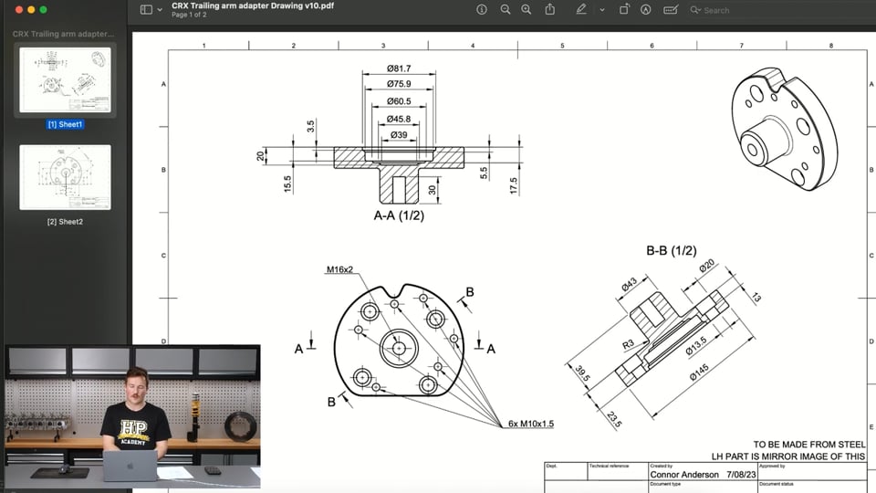
| 10:10 | So an alternative to using a camera, the other options we talked about before is using an orthographic projection drawing so here's an example of a quick one I was working on yesterday for some parts for the CRX. |
| 10:28 | If we look at this part up in the top right corner, we get this isometric view of it and then we have our front, top and a section, well they're both section views here but these are orthographic projections so we have no perspective distortion on them. |
| 10:46 | And these are a great tool to use for one because they have no distortion but sometimes it can be really helpful to use a drawing like this as a canvas to model around because they also have the dimensions shown on them so we can easily scale them to the right size. |
| 11:09 | Again this will make a bit more sense in a moment. |
| 11:14 | And I'll just jump over to the other drawing I had here, they're also very helpful because we have multiple views of the parts and we can set these up on our planes in CAD which again I'll show you in a moment. |
| 11:29 | And this gives us multiple views that we can look at the part from each side and copy in each direction. |
| 11:39 | Now the final alternative to the camera image is what I've got shown in this photo here and this is the parts placed on a flat bed scanner and a really kind of handy tip here is to also place a ruler which is shown here, on the bed of the scanner as well and we'll be able to work off that and use that in the scan to scale the image which again I'll show you in a moment, but this is a really good way of getting a image with no distortion as well. |
| 12:17 | If for example in this image we're just trying to copy these two flanges here, get the spacing of the holes right, get the spacing of each flange correct and match the edges, we would get an image that we can copy with no distortion on it but I'll show you an example of that in just a moment. |
| 12:39 | So at this point I'll just make a quick call for questions, if you have any questions around this, feel free to drop them into the chat and I'll do my best to answer the at the end of the webinar. |
| 12:52 | So let's have a little look at Fusion 360, I'll just close this so we have a new document. |
| 12:57 | Now I'll just show you how to get a canvas set up in Fusion 360 that you can use to model around. |
| 13:04 | So if I go over to the insert tab here and click on that, I can drop down and have canvas here. |
| 13:14 | So as the little blurb says here, place an image on a planar face or sketch plane, so that's just basically a flat face we can place an image on so if I click that, it gives me the ability to access, these are files that are in my workspace. |
| 13:33 | I'll just make a quick note here as well, I much prefer using our PNG files for my images rather than JPEG. |
| 13:44 | Sometimes I find when I bring JPEG images into CAD, specifically Fusion 360, they tend to distort or not stay to the right scale, PNG files just prove to work a little bit better. |
| 13:59 | So if we look at this image here, this is a strut tower front view and I'll just click insert here and I'll click the front plane here and we'll apply that image to that plane. |
| 14:14 | So I'll just click OK there and I'll zoom in on this and look directly at it and you can see that this is the strut tower inside th engine bay of our FD3S RX7, Mazda RX7 and this is looking straight at the front of the strut tower. |
| 14:34 | So I just took this image on my phone using the highest focal length lens from a little bit of a distance back and just looking directly in line with that top mounting surface there. |
| 14:50 | Hey welcome back, sorry about that, we just had a little technical difficulty. |
| 14:53 | So back on my computer screen now we are looking at a photo I took with my iPhone of an RX7 engine bay, the strut tower specifically and this photo was taken looking straight onto that with my iPhone with the focal length of the lens at the most zoomed in option to minimise the distortion. |
| 15:16 | So I took some measurements while I was doing this to be able to scale it to the right size so if we just come over to our browser here and drop down here and then I can right click the canvas and click calibrate. |
| 15:32 | If I zoom in a bit, I took some measurements so I know that that distance from the bottom of basically the mounting face here to the top of the stud is about 23 mm. |
| 15:44 | So you can see there as I've brought the image in, it's about 0.9 mm and if I type in 23 here, it's going to scale this image up significantly. |
| 15:55 | So now it should be about the right size and I can make another check here because like I said, I took measurements in multiple directions to make sure the image wasn't, didn't have too much distortion so we wouldn't be able to use it. |
| 16:10 | So I know that these are M10 bolts here so the distance across the threads is going to be about 10 mm, little bit less but that'll be fine for this example so we know it's pretty close. |
| 16:24 | Before moving on, what I'll do is I'll just click edit the canvas, I'm going to show the origin just so I can line the next one up with the same spot and I'm just going to drag so the origin point, this text is in the way, is just at the base, it's in the way again, of that bottom bolt hole there. |
| 16:49 | And click OK. |
| 16:51 | So before moving onto the next one I'm just going to quickly create a new plane that is in line with the surface of the top of the strut tower here. |
| 16:59 | So if I just click the plane at an angle tool, choose the Z axis here and then look at it from side on, drag this up, about -12 is going to line that up nicely with that surface. |
| 17:17 | So this plane suits that top surface of our strut tower. |
| 17:23 | So now I'm ready to add my next canvas in and I'm going to choose the strut tower top view and I'm going to click insert and choose that plane that I just created. |
| 17:37 | Just wait for this to load, and this next image is like it sounds, it was just taken looking directly at that top surface of the strut tower, if it loads. |
| 17:55 | There we go, so again it's come in very small and we need to scale that up to the correct size. |
| 18:01 | So I can just right click that plane we're created and choose look at to look directly at that plane, this will make things a little bit easier. |
| 18:10 | Right click that canvas again and choose the calibrate tool. |
| 18:14 | Then I took some more measurements here and I know that the spacing of these bolt holes is, they're all 95 mm spaced apart so these three bolts are mounting the strut to the strut tower, are 95 mm centre to centre. |
| 18:32 | So if I just click on the centre there and the centre here, see at the moment it's 6.77 mm and I can just change that to 95 and that's going to scale things up a bit. |
| 18:44 | And same thing, I'm just going to check in another direction, can see we have some distortion here. |
| 18:54 | Just from it not being perfectly long focal length and for direction of the photo but it'll be enough for its use so if I just click on the centre point there, the centre point here, 94.97 so basically 95 mm as well. |
| 19:16 | And then the last thing I'm going to do is jump back in and edit that canvas, I'll just jump out of that, one moment, choose to look at the plane it's on again. |
| 19:29 | Edit the canvas and I'm going to do the same thing where I'm going to drag that bottom bolt hole to centre it on the origin which is this point here. |
| 19:41 | Then now we have, sorry drag this around a bit, two canvases set up and they are lined up with each other and to the correct scale and from here we could use this to design something like a strut tower brace or at least the bases for a strut tower brace so starting for example we could sketch on that plane at basically just locate these holes, sketch circles around them, doing this really rough and quick and do something like that, finish the sketch and then extrude that up and start designing our part from there. |
| 20:32 | So that's a quick example of using photos for a canvas and we'll move onto some other examples of the two other options we have which we've discussed. |
| 20:44 | So the next one will be taken from a 2D flat bed scanner. |
| 20:50 | So I'm going to use the same process here, insert the canvas and I'm going to choose this here, I've got a regular bracket one and two and I'll start with number one. |
| 21:02 | Insert this image onto the top face and this is just a scan that I took of a small bracket with a 90° bend in it and it's yeah a bit of a regular shape part, that's perfect for scanning. |
| 21:22 | So like I said when we were discussing before, you can place a ruler in the scanner like I showed in that image and that can help us scale it so that's exactly what we're going to do here, using the canvas, under the canvases, right click to use the calibrate function and then if I zoom in here and click on the 10 mm part and then scroll up to somewhere, the bigger distance we can calibrate across, the more accurate it's going to be. |
| 21:51 | So scroll up here, 10 mm to 110 on the ruler so obviously 100 mm apart, we can just scale that up and I'm pretty comfortable not checking two dimensions in different directions on this 2D scan because I know that the distortion on a 2D scanner is going to be negligible really. |
| 22:13 | So before moving on I'm just going to edit this canvas and do a similar approach, show the origin and just rotate it slightly around, drag this face up to there, can get a bit more rotation just so the centre of that face which is where the bend is for the part is sitting on the origin point. |
| 22:44 | That'll just make it easier for us to line the other image up with it. |
| 22:48 | So we're going to do that now, going to insert the canvas again, click our second part and then we're going to put that onto this face here, this plane sorry, wait for it to load again, depending on the size of the images, how fast your computer is, your internet connection, this can take a moment. |
| 23:11 | So now we have that image here, again it's really small, right click here, calibrate the canvas and we'll look straight onto that, make it a bit easier, same process, zoom in, click on the 10 mm mark and then on the 110 mm mark, set that at 100. |
| 23:39 | Then same process here, so edit that canvas and then we want to drag it so we get that point there lined up in the centre and then basically there we've created the part and then we can jump in, sketch, and start basically tracing it out, pretty easily there and just copy the profile of the shape to recreate it. |
| 24:23 | Because for example this part is just a little part from an engine bay I think and if it was broken for example, it'd be quite difficult to get another one so it's easier to just scan what we have of it, recreate it and then we can just get that part plasma cut or laser cut, bend it back up and then we've got another one that's exactly the same ready to go. |
| 24:48 | So you just keep tracing around that, create a sheet metal part, create a flat pattern, create a DXF from that and then get that part laser cut. |
| 24:58 | So that's the process there and we'll move onto the final one which would be using a orthographic projection or technical drawing. |
| 25:05 | This time I have these parts on my computer so rather than looking in the project folder, the alternative is to look in the files on your computer so if I jump into CAD here, go to CRX, we have a Wilwood DynaPro single piston or dual piston calipers on the back of the CRX and previously I had to model them up for modelling the rear brake caliper brackets so this is just a good way to rather than taking a lot of measurements of the calipers themself, on the Wilwood website I was able to find these technical drawings and it's just a good way to use those as a reference to create the model from. |
| 25:58 | Of course I wouldn't recommend taking someone's technical drawing and copying it for the purpose of basically counterfeiting their design but in the case of this where I just created a very simple representation of the caliper to create my caliper bracket around, it works perfectly. |
| 26:20 | So I have two technical drawing views here with dimensions on them and I can choose either of those and bring them into my workspace, apply them to a plane and then view that straight on, same method, calibrate and then can use the dimensions that they have here which are shown in millimetres of inches, they're missing a few here like the ones with letters because they have a table for the different variations of the calipers but we can use this top one really easily here and here. |
| 27:03 | Calibrate across that distance and we could put 121.4 mm in here 'cause we're working in millimetres as my primary units. |
| 27:15 | Or alternatively if I just put 4.78 and then the little semi colon or whatever that thing's called, inches sign, that will scale it to that many inches and then that is there scaled and the same process from there on where I would bring in the other view of the drawing, line it up and then can basically start sketching around that, using that as a reference and building my 3D model from there. |
| 27:44 | So that is the fundamentals of using canvases for our CAD projects and just a quick way to do that and save a lot of time measuring the parts and make sure we understand that they're going to fit and how they're going to fit together as well. |
| 28:02 | So I'll just jump over to my notes and see if there's any questions. |
| 28:10 | Hopefully I can answer. |
| 28:16 | So Mark W just says, some OnShape content would be great, it's very good, is that something that we'd do? Yes definitely is, I did a webinar two or three weeks ago where we did an introduction to OnShape so if you haven't seen that, that's worth checking out. |
| 28:33 | In the future we are going to be doing some more OnShape work as well, hopefully do some worked examples to go along with our CAD course and more webinar topics like that so if there's anything in particular that you want to dive deeper into with OnShape or any other CAD program, any other CAD programs you want to look at, just let us know and we'll do our best to get to them. |
| 28:55 | We're going to try to cover all the main accessible ones as they kind of become available as well and as people would like to learn about them. |
| 29:05 | In saying that, if you are out there and you're wondering about the differences between OnShape, Fusion 360, Solidworks, the other ones, we have some webinars where we have discussed those before and the best thing of course to do is to just get started with whatever you can. |
| 29:23 | We recommend Fusion 360 if you're going to follow along with our course and then once you pick up the skills using the free version of Fusion 360, you can transfer those to any CAD program, they're all very similar and the skills are definitely interchangeable. |
| 29:40 | That looks like the only question that we've got today so thanks for watching and as I discussed, we will be covering some more CAD topics in the future as well. |
| 29:51 | So we'll see you in next week's webinar, cheers. |
Timestamps
0:00 - Introduction
0:50 - Canvas forms
1:35 - Where we would use a canvas in motorsport
3:22 - Needs to be adequately detailed and correct scale
4:33 - Minimising camera perspective distortion
9:34 - Take measurements in multiple directions
10:10 - Camera alternatives
12:52 - Photo demo
20:43 - Flat bed scanner demo
24:58 - Technical drawing demo
28:02 - Questions


