333 | MaxxECU MTune Software Tutorial Plus Tips and Tricks
Summary
In this webinar we will explore the MaxxECU MTune tuning software and see how it can be used on the dyno to help us quickly tune both the fuel and ignition timing. We will also look at some tips and tricks that you can incorporate to get better results from the software in less time, while also helping to ensure engine reliability.
| 00:00 | - Hey team, Andre from High Performance Academy, welcome to another one of our webinars and today we're going to be diving into the world of MaxxECU, specifically the MaxxECU MTune software, the user interface that you'll need to tune the MaxxECU range of ECUs. |
| 00:17 | And just like any platform, there is a bit of a learning curve involved with getting your head around how it works, where all the features and functions are, how to get the most out of it and then obviously how to actually make your tuning changes so the intention with this particular webinar is to fast track your learning here so that you're going to be familiar with it. |
| 00:38 | Also bring in some tips and tricks that you can use in your day to day tuning that are going to fast track the process. |
| 00:46 | So I don't necessarily say at the end of this webinar you'll be a pro with MTune but it should definitely make your life a lot easier and speed up that learning curve. |
| 00:55 | As usual, we'll have questions and answers at the end of the lesson so if there's anything I talk about or anything related to this specific topic that I didn't cover and you want to ask about, you can ask those questions in the chat and we'll get into those at the end. |
| 01:09 | So the vehicle that we've got running here is a Honda City powered by a B18C Type R naturally aspirated engine out of a DC2 Type R Integra so it's naturally aspirated and it's nothing particularly unusual, completely internally standard but it's going to be a perfect test bed for our webinar today. |
| 01:32 | We'll start witih a quick tour and at the moment I am offline, we don't have the engine powered up and we can see that if we jump across to my laptop screen, because up here we've got this little status bar, that's currently grey and it's showing that we are offline and just to prove a point, we'll power everything up and we can see at the moment it's showing us the ECU and in this case the PDM is online. |
| 01:55 | Turn it back off just so we don't flatten the battery while I'm doing this basic introduction here. |
| 01:59 | So this is an element with the MaxxECU, they do have an optional PDM, certainly don't have to go down that path but it does simplify a lot of your wiring and the MaxxECU and PDM do communicate nicely together as a nice little pair so makes it really seamless. |
| 02:17 | The integration is seamless and also the programming of the PDM is done from inside the same MTune software, meaning that you aren't using two different pieces of software to tune your ECU or calibrate your ECU and your PDM. |
| 02:31 | We're going to ignore the PDM, power distribution module for the rest of this webinar though and pretend it doesn't exist because really we're focusing on the tuning software itself. |
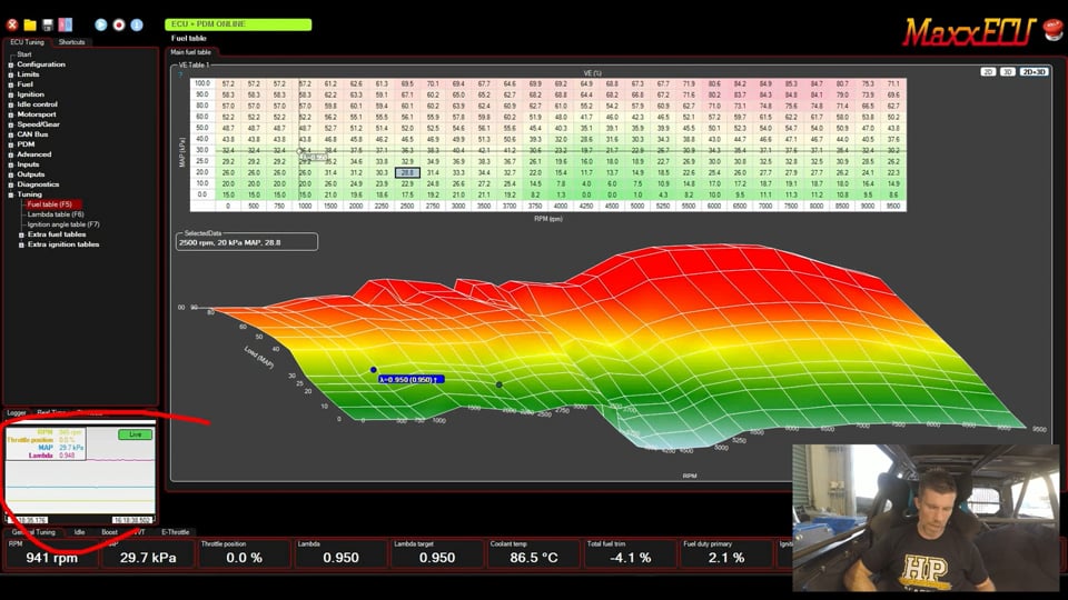
| 02:43 | So as we're looking at it right now, we've got a couple of elements that we need to talk about, so this is our fuel table, our main fuel table here. |
| 02:52 | So this is volumetric efficiency based and we've also got our, we'll talk about the fuel table and go through some tuning processes on it really shortly, we've also got a menu structure out to the left hand side here which is how we can navigate around and basically find all of the inputs, outputs, configuration options that we need. |
| 03:13 | Down the bottom we've got a couple, or three options here, we've got at the moment, our real time parameters or channels list so obviously again we're not live at the moment but if I just flick this back on, probably left it on, we can see we're getting real time values for all of the channels, so look at our analog input channels here we've got three pressure sensors and we're seeing the actual values on those, we can see raw voltages and basically the same goes for just about everything else so this is a great way of getting some really deep insight into specifics of what's going on with all of your inputs and outputs. |
| 03:50 | More useful I guess really when you are getting into fault finding as well but that is something that you definitely need to know about. |
| 04:00 | Then to the left of this, if I click on this, we've got our logger option which we are again going to see in use once we get the engine back up and running so this is really really powerful, it's a built in logger and we can record all the channels we want, at the moment we've got let's see, four channels, RPM, throttle position, manifold absolute pressure and lambda being logged but of course we can add or subtract that as we see fit and then once we've got some logged data, so how I'll conventionally use this is during a ramp run on the dyno I'll have that logger running, we will then stop or pause that logger after the ramp run and then we can go back, cycle through the data in our log file and we'll also see up above essentially a ghost cursor showing exactly where the ECU was accessing in any of the tables at that particular snapshot in time. |
| 04:51 | Makes it really really easy to fast track your calibration and get everything dialled in nice and accurately. |
| 04:59 | Down the bottom here we have a little bar of gauges and again, probably should have left the thing up and running but got a tiny battery in this car, you'll see this in action once we have the engine running which makes everything a little bit louder so for the moment I'm leaving it off. |
| 05:13 | But basically any of the live parameters that we want to see. |
| 05:18 | So we've got a various tabs here as well so at the moment I'm on general tuning, I've also got a tab for idle, boost, VVT and E throttle but basically you can use these for whatever you want and basically add the correct gauges to each of these tabs to suit that particular aspect of your tune and obviously this is really going to come down to your own personal preference. |
| 05:40 | So that's the high level, up the top here we also have some other parameters here, some other tools I should say, we can open, say if we can compare, we've got an auto connect will work online and then we can also open or download log files once we're online. |
| 05:57 | So that's the high level quick and dirty view of the MTune software. |
| 06:03 | I'm not going to go too deep into each of these elements, this isn't an all encompassing software tour because I've done an introduction to MTune before, this one I want to get a little bit deeper in some of the specifics but I am going to cover a little bit of the same ground. |
| 06:19 | First element to really understand with the MaxxECU is it is a volumetric efficiency based ECU. |
| 06:27 | And this is pretty common these days, the VE based tuning model is probably the most common. |
| 06:34 | So it's probably something that most people getting into tuning these days would be pretty familiar with. |
| 06:40 | That wasn't always the case though, this has really come to the fore over maybe the last six or seven years and everyone sort of jumped on that VE based tuning bandwagon. |
| 06:49 | Not to say it's better or necessarily worse, prior to this a lot of ECUs used injection time based fuel tables and the important element and why I raise it is with a volumetric efficiency based fuel model, it's really important to understand how the ECU actually works, basically the logic flow and this starts with giving the ECU some important information in order for these VE numbers in this table here to be useful or accurate or somewhat meaningful, we need to make sure that the basic parameters are set correctly, otherwise we're just going to end up baking errors into this VE table and then all of our corrections aren't going to work as well as they potentially could. |
| 07:31 | So this starts with our configuration, so we'll come back over here and obviously we can expand any of these menu items as we need to and we'll start with our ECU settings. |
| 07:43 | So in this case we've got a piston four stroke engine, four cylinders and really the important element here is our engine displacement. |
| 07:52 | This is a B18C as I mentioned, 1800 cc capacity. |
| 07:57 | Probably more like 1797 but I'm not here to split hairs. |
| 08:01 | But this is really important, basically it tells the ECU what the capacity of the engine is and then it can obviously break that down into the capacity of each cylinder. |
| 08:10 | Where this can go a little bit off the rails is if we've got a built engine that has a stroker kit fitted to it. |
| 08:19 | Now I'd like to think that we're always going to know that but maybe that's not the case. |
| 08:23 | Particularly if you are commercially tuning for customers and maybe the customer doesn't tell you all of the information of maybe the customer's bought the car and doesn't even know so things like that can really affect the accuracy of our VE tuning so not only do we need to tell the ECU what the engine capacity and number of cylinders is, we also need to tell it about the fuel system so let's come back down to fuel and if we come down to fuel general here. |
| 08:52 | Key elements in terms of just the volumetric efficiency side of things, we need to tell the ECU what the stoich air/fuel ratio for our fuel is. |
| 09:01 | So in this case we're running on gasoline which is 14.7, got a drop down menu here so E85 would probably be another common option or we can even go with a custom setting to suit whatever fuel you've concocted in your home chemistry lab. |
| 09:16 | So once the ECU knows that, it knows essentially what mass of fuel and air needs to be combusted in order to achieve a stoich air/fuel ratio of 14.7:1. |
| 09:28 | Or lambda 1.0. |
| 09:30 | The other element that's really important here is the injector settings. |
| 09:34 | So we need to make sure that we have told it what size injectors are fitted and essentially how this works is if the ECU knows what size injectors are fitted, or in other words, it knows for a given pulse width what mass of fuel it can deliver, it knows what our target air/fuel ratio is, which we're going to go through in a minute and then basically we can calibrate the volumetric efficiency table, we're essentially telling the ECU at that particular point in the table what mass of air is entering the engine or in other words how completely the engine is filling its cylinders with air. |
| 10:08 | So why the VE based tuning model? Well there are some advantages, these advantages really come in particularly when we are doing flex fuel tuning because for all intents and purposes, the volumetric efficiency of the engine doesn't change, or it doesn't change very much as we move from pump gas to E85 to E100 or anywhere in between. |
| 10:31 | So technically all things being equal we should be able to tune a flex fuel engine with simply one VE table. |
| 10:39 | Now there are some caveats around this, even the injector flow actually varies depending on the viscosity of the fluid which varies between gasoline and ethanol so that doesn't actually hold true perfectly. |
| 10:50 | But rest assured it does make your tuning much simpler than having an injection time based ECU where essentially you're going to need to manually increase the fuel delivery by around about 38%, 40% as you move from pump gas to E85 so a lot more work to do for the tuner. |
| 11:09 | The other element which is also the next point that we need to talk about is that if you decide you want to make an air/fuel ratio target change, you don't have to change the VE table to achieve that so let's go back into the laptop software. |
| 11:24 | If we go down to tuning, we've got three main tables and this is where we're going to be spending the majority of our time. |
| 11:29 | We've got our fuel table which we've already seen, we've got our ignition table which right now doesn't matter and then we've got our lambda table, lambda target table more specifically. |
| 11:39 | So this is important for two reasons. |
| 11:42 | First of all this is the backbone of the VE based fuel model. |
| 11:47 | We must start by setting our target lambda table to the actual air/fuel ratios or lambda targets we want the engine to run. |
| 11:56 | So if you don't know about this or if it's just left to default values, you might have a value in here at wide open throttle and 4500 RPM, you might have that set to 0.80 just in a default map, I don't know, whatever it could be and if for example you actually want the engine to be running at that site 0.90 lambda, you're going to be fudging the VE table in order to get that difference and it's going to make your VE table look really weird and also it's going to mean that the next trick that is an advantage, you can't use. |
| 12:30 | So that trick, let's take this back to 0.90 so let's say with our naturally aspirated Honda K20, we're, for all intents and purposes going to be running through this 100 kPa row of our target lambda table under wide open throttle, give or take. |
| 12:48 | Obviously there as we can see, I'm targeting a flat line of 0.90 just for the sake of simplicity. |
| 12:54 | So let's say that we then dial in our VE table so we come back to our VE table over here and that corresponds to this same row here, 100 kPa. |
| 13:05 | So we've tuned each of these individual sites very carefully and accurately on the dyno to the point where they actually do result in a target lambda being achieved, 0.90. |
| 13:15 | Then the advantage with doing this is let's say we want to see what the engine does if we richen it up a little bit, let's say we want to see how it performs at 0.88 or 0.86 lambda. |
| 13:26 | Rather than making individual cell changes here, all we need to do is go to our lambda target table and we can now choose the entire row here, let's say we want to go 0.88 and if we've done our job properly we've entered the correct data, there's no more work to do, the ECU will do that heavy lifting in the background and we can run the engine up on the dyno and we should achieve 0.88 lambda or whatever we've set it to. |
| 13:50 | So that is quite a nice function with the VE based tuning model but the essential part that I'm trying to get here is before we can tune it, we need to get that base set up correct, we need to tell the ECU the engine capacity, the type of fuel we're running on an what sized injectors are fitted. |
| 14:07 | If we don't do that then we're just going to be baking in those errors. |
| 14:13 | Alright the other element that the air/fuel ratio target table is used for of course is closed loop fuel control if you decide you want to run that. |
| 14:22 | So basically the idea behind this is that we'll tune the VE table, generally I'll turn it in open loop but not always necessary and we'll achieve our target air/fuel ratios and then once we've done that we can enable closed loop control and this is just there to kind of pick up the pieces if maybe day to day variations in atmospheric conditions result in small fluctuations from our target. |
| 14:47 | So the ECU can just add or subtract fuel, got a lot of control over how that will work as well. |
| 14:53 | Before we get into that though, let's just have a look at those inputs. |
| 14:56 | So we'll come down to inputs here and lambda sensor, one of the really nice features with the MaxxECU or this particular one is that it does have a built in lambda controller onboard so you can wire your lambda sensor direclty up to the MaxxECU, no need to purchase a external analog or CAN based wideband controller and then wire that to the ECU. |
| 15:21 | So let's just quickly go over these features here. |
| 15:23 | We are using a single sensor here, it is an internal wideband controller on channel one. |
| 15:30 | The other element here is sensor warmup and this is something that is overlooked I think. |
| 15:36 | Probably most people who have been in the tuning industry for a while will have heard horror stories about life expectancy of lambda sensors and this really was a very big problem probably more of a problem about five to 10 years ago. |
| 15:51 | A lot of it comes down to the fuel you're running on, if you're using heavily leaded fuels, and I found this when I was tuning a lot of drag cars running C16 and Q16 race fuel from VP, heavily leaded, works amazingly well on high boost turbocharged engines with octane somewhere in the 120+ vicinity, give or take, the problem with that is that the lead destroys these sensors and I could go through a brand new LSU 4.2 sensor which was the option available back then, in sometimes as little as 10 to 20 minutes which is pretty gutting for a sensor that back then was probably still $300 or there abouts. |
| 16:29 | So the other element, even if you're on a non leaded fuel is that moisture condensing on that sensor element which is glowing red hot, can quickly destroy it so you want to be careful about how that works so where I'm going to is this ECU, sorry sensor start warmup option here, at the moment ECU startup. |
| 16:51 | So if we look at this drop down menu. |
| 16:54 | We can have it on engine startup, ECU startup, or delayed startup. |
| 16:58 | Now the advantage of having on ECU startup is essentially as its name implies, the second that you power the ECU up it will start running the sensor. |
| 17:07 | This is great because the second that we then crank the engine, we are going to be getting valid lambda data, air/fuel ratio data. |
| 17:15 | So it's really good for analysing the cranking, cold start, immediate warm up enrichment, otherwise it would take the sensor maybe 20, 30, 40 seconds to come online and you've lost a lot of that initial data on that cold start. |
| 17:29 | But it does open the sensor up to premature failure as a result of the condensation being blown through that exhaust onto that hot sensor element. |
| 17:39 | So engine startup, as its name implies, will run the sensor but not until the engine is actually started, and it will shut down the sensor, in this case 120 seconds after the engine stops. |
| 17:50 | Or alternatively you can delay the sensor as well, the sensor startup, to suit your own requirements. |
| 17:57 | So for the moment for our demonstration, we'll leave that on ECU startup but it is overlooked, if you do want to get good sensor life I would absolutely recommend that after the tuning's complete, you change it to engine startup or for that matter even delay the sensor startup. |
| 18:09 | Moving down, the other element here is the sensor type and it does actually warn you about this here. |
| 18:17 | If you've got this set incorrectly it will damage the sensor so make sure that on your initial startup, you've got your sensor unplugged, set this, adjust it to suit the sensor you are using, then you can plug the sensor back in. |
| 18:30 | Alright so that's the built in lambda sensor. |
| 18:33 | I mean it's not groundbreaking, let's be honest but I really do like an ECU that has built in wideband control. |
| 18:41 | It just means that A, you're saving a little bit of money in terms of not needing another external module, that also simplifies the wiring and installation, it's all built in and with a built in lambda controller like this, or a CAN based controller, the same could be said for, it also removes the potential for ground offsets affecting the accuracy of the lambda value and this is something, those who have taken our courses, listened to our webinars will know I do harp on about this but I've had such bad results with analog voltage based lambda controllers or wideband controllers that I just won't use them anymore. |
| 19:17 | Yes there's some steps you can take to mitigate a lot of that but ultimately it still just opens you up to the potential for ground offsets that can affect the accuracy of the air/fuel ratio reading you're seeing and that in turn can obviously affect the potential for reliability of your engine. |
| 19:33 | Alright let's shut that down. |
| 19:35 | So we've got a lambda sensor fitted and wired up and all of our settings are correct, if we come back to fuel and we come down to lambda control, this gives us a lot of control over the way that wideband works, wideband control works. |
| 19:50 | So our controller type in this case, obviously wideband and our target is our lambda target table, got some other options in here but essentially wideband or disabled is going to be what we want. |
| 20:01 | We can also set some parameters for when the feedback, the lambda feedback will work. |
| 20:07 | In this case coolant temperature or minimum run time. |
| 20:11 | Generally because it is a wideband controller, once it's up and running, it's working, I will generally allow it to use lambda control during startup or warmup as well, I don't really see a downside to doing this. |
| 20:25 | We also have transient deactivation so basically on transient conditions we're going to see almost certainly a error momentarily in our air/fuel ratio and we don't necessarily want the wideband trying to actually track and control that, that's going to end up with basically us ending up going too rich or too lean once that transient event has expired and we're back to normal running conditions so we can disable that. |
| 20:51 | We've also got a reactivation delay on that basis and then our lambda regulation, so essentially how often is it going to look at the lambda sensor feedback and make a change? So what we can see here is we've got frequency in cycles per second relative to our engine speed. |
| 21:06 | Down at idle, it's probably actually a little bit high there at three, I'd sort of go one to two cycles per second so basically it's looking once a second at that sample. |
| 21:16 | Then at the top end here we've got six, that actually might be a little bit light, we could probably bump that up to eight or 10 so the theory here is that at idle, we've got low exhaust gas velocity so basically it takes a longer transport time for the combustion gases to exist the cylinder, travel down the exhaust manifold and make its way to the sensor. |
| 21:36 | So if we have our update frequency set to high at idle, what that's going to do is basically, let's say we're running a little bit lean, so the ECU will add fuel, immediately it will sample again based on that frequency, the change actually hasn't had time to take place and be sampled by the lambda sensor so it's still going to read lean so the ECU will add more fuel, the cycle continues and basically by the time the sample has actually made it to the lambda sensor, we're already going too rich and then we end up with this gentle oscillation as the ECU tries to add and subtract fuel so really important to match that frequency and probably what I've got there is not a bad starting point now, around about 1-2 samples per second at idle and then somewhere around about six to maybe 10 at high speed. |
| 22:23 | If you're starting to see this oscillation in your control, that generally would suggest that you've got some problems there with your sample frequency or lambda regulator as MaxxECU refer to it. |
| 22:34 | The other element here is you can control the maximum and minimum trim available which is a really really nice feature. |
| 22:42 | Now I know a lot of tuners are a little bit apprehensive about using full time closed loop control in case the sensor fails or something like that. |
| 22:50 | There is built in diagnostics around the sensor as well, another nice feature of having the built in wideband controller rather than a separate analog controller with no diagnostic feedback but what we can see here is in this one here, maximum negative correction. |
| 23:04 | So at low manifold pressure and from up to 3000 RPM, I'll allow it to trim out 10%. |
| 23:11 | In the idle areas, particularly when the engine's heat soaked, we're quite likely to see a requirement for larger variations in our lambda control. |
| 23:18 | However at wide open throttle, higher RPM, I've trimmed this to -5%. |
| 23:22 | And we see the exact opposite on the other side, the positive trim. |
| 23:25 | So you can essentially do whatever you want. |
| 23:27 | Maybe you want to allow a lot of control in the idle and cruise areas, maybe +/-25%, pretty typical with a OE vehicle that that would be the case, and then you might want to pull that down to maybe +/- 2-3% at wide open throttle. |
| 23:40 | This, remember is not a bandaid for doing your job properly and tuning the fuel table, this is really there just to pick up small inaccuracies that creep in day to day so you can basically do as much or a little with that as you want. |
| 23:55 | Alright so fuelling dealt with. |
| 23:57 | Again I'm not going to cover everything here, just some of the aspects that I think are unique and important. |
| 24:03 | We'll come back down to our inputs and we'll come to our trigger and our home inputs. |
| 24:08 | So again this is not groundbreaking but I just wanted to explain this. |
| 24:13 | So we are dealing here with a variable reluctor sensor or magnetic sensor on our Honda, just factory. |
| 24:20 | So we can see here we've got some settings, our trigger sensor type, so we've got a VR sensor zero crossing, if we drop down our menu we've got the option to go with a digital which is a hall or optical sensor or a VR sensor that's bipolar. |
| 24:35 | We've got the right setting there. |
| 24:38 | Typically VR sensor, zero crossing or our digital would be the most common. |
| 24:44 | Then we can choose our trigger polarity so this is which edge of the signal we are triggering off. |
| 24:52 | Falling is typical and a lot of ECUs for a variable reluctor or magnetic sensor, this isn't adjustable. |
| 24:58 | This is nice that it is because it allows us, if we've got the wiring polarity around the wrong way, instead of changing the wiring polarity we can just change this setting. |
| 25:06 | Really critical to get the polarity correct because if we don't we're going to end up suffering from timing drift. |
| 25:13 | The point that I wanted to talk about here is the arming voltage and we can see here this is set to manual table which is this. |
| 25:22 | So the point with the variable reluctor magnetic sensor is that the amplitude of the signal will change depending on the engine speed. |
| 25:30 | And what we want to do is basically set a arming threshold and how this works is that the ECU will wait until it sees the voltage exceed that arming threshold. |
| 25:41 | Before it starts arming and it's basically saying to itself, alright I know I'm getting ready for a trigger event to occur, and then it will actually trigger once that signal drops back through zero, so that's the zero crossing. |
| 25:53 | The idea behind this is it helps eliminate background noise, so it won't trigger off background noise which is always going to be present no matter how well you've wired your car up. |
| 26:04 | The other element though is if we set this value too high, it'll ignore valid signals so I just want to quickly draw this out so you can see how this works. |
| 26:14 | Now this is going to probably be a pretty horrible drawing but I'll do my best. |
| 26:17 | So if we've got our axis of time on the horizontal axis and we've got voltage on our vertical axis. |
| 26:25 | So a typical VR sensor signal will look something like this, it's coming along at zero as the tooth comes closer, it will climb up, it will peak and then it will drop back through zero and then what it's going to do is basically a mirror image of that and go back to zero so that's essentially as our tooth goes past the sensor. |
| 26:48 | So how that all works is that arming threshold that I mentioned, generally we want to set this at about a third of the peak amplitude so again I'll just draw this in, maybe it might look something like this. |
| 27:01 | And when that voltage crosses that threshold right there, this is when the ECU's armed, it knows that a trigger event is going to occur and then as I mentioned it will trigger at this point here where it goes back through zero. |
| 27:15 | So the point is that we need to set up this arming threshold table and I know this is something that a lot of people do get wrong. |
| 27:23 | Because we have to come up with these numbers and while yes there's generally going to be a generic setup for this table that in most cases will get you by, this actually makes it worse because most tuners don't bother and then when they get a car that won't start or they've got trigger issues, they don't know what to do with this table so you can see that again we've got 700, 1600, 4000 and 4500 RPM and we want to set at each of those points the voltage at about a third of the peak amplitude value. |
| 27:55 | However, and a nice feature, if we drop down this menu here for arming voltage, the ECU can also do automatic tracking, in which case it basically does that for us, we don't have to set up an arming threshold table, the ECU will basically look at the peak amplitude and automatically adjust the arming threshold point to the optimal point. |
| 28:13 | So nice feature there, I won't go through too much more of this but the other element that I did want to talk about here is our diagnostics and our trigger oscilloscope. |
| 28:25 | So this can be used to manually set that up. |
| 28:29 | So what I'll do here is we'll just get the engine up and running. |
| 28:34 | And we'll just do a quick measurement here so we'll start that and stop it and basically this, just like any ECU that has an oscilloscope function, will give us a real time oscilloscope view of the signals going into the ECU. |
| 28:53 | So up here we've got our trigger input which is our multitooth and then down the bottom we've got what they refer to as home or cam, which is our synchronisation input. |
| 29:05 | So the point with this is we can see here that this doesn't quite look like what I drew. |
| 29:14 | In fact it's the polar opposite, it's an inverted signal. |
| 29:17 | So this is important because if we come back to our inputs and our trigger inputs, we can see I mentioned the shape, I drew that shape of a conventional signal and that always triggers off the falling edge. |
| 29:35 | In this case the wiring for our home signal is actually inverted but we can simply change the home polarity to rising so actually really nice and easy. |
| 29:45 | Now if we come back to our scope function here as well, we can see that the ECU, the scope function actually shows a little crosshairs at that zero crossing point where the trigger has occurred. |
| 29:58 | So we can see exactly where the ECU is triggering, we can also treat this like any other oscilloscope and we can zoom in and change the adjustments to suit. |
| 30:10 | What we can see here though is our peak amplitude, in this case we're going down to about negative -1.7, that's a horrible line I've just drawn in, -1.7V and about +0.7V. |
| 30:23 | Two and a bit volts on each side of our main trigger input so again we can use our trigger scope at cranking and at various speeds to help more accurately fill in that manual trigger arming threshold table if desired. |
| 30:40 | The other element that the MaxxECU has, very similar to the trigger oscilloscope but we've also got a trigger logger. |
| 30:49 | So the trigger oscilloscope is just like hooking up an oscilloscope at the header plug of the ECU. |
| 30:56 | We're actually seeing the raw input from the trigger sensors, the trigger and home sensor so that's what's being fed into the ECU but then depending on the trigger setup in the ECU and depending on our settings like our arming threshold, that's not necessarily what the ECU is seeing and using to process its trigger decisions so if we look at our trigger logger and again that's just cycling along there, we can stop it, we can save this to a file, we're seeing exactly what the ECU is decoding. |
| 31:30 | Not a lot to see here because this isn't a missing tooth input but if we've got a missing tooth input it'll show us the gap between the teeth, we can make sure that everything's correct here and we can see everything's green at the moment which is good. |
| 31:43 | If there was something wrong it will show us with a red bar showing that it's maybe missed a trigger input or something like that. |
| 31:51 | Likewise another little tip that I'll show you here, it's down in the bottom right hand corner, we've got this parameter that we're monitoring which is called lost sync count. |
| 32:00 | So if you're running the engine on a dyno and maybe at higher RPM you're starting to get an ignition misfire, this can be quite difficult to diagnose, it might be exactly that, it might be an ignition misfire. |
| 32:12 | Maybe you've got a weak ignition system, maybe your spark plug gap is too wide or a million other things. |
| 32:19 | But it can also be that the ECU's actually running into triggering problems and by checking that lost sync count, that will be an indication if there is a trigger problem, we can use our trigger scope as well but, trigger logger as well, the idea here is that quite often during initial cranking, we will see our lost sync count increment, might get to one, two or three but once the engine's up and running and synchronised, that should not budge. |
| 32:47 | So if we do a ramp run on the dyno, we look down and we see that that lost sync counter has incremented by five or 10, that is a warning sign, something there is not right. |
| 32:58 | OK we'll leave the engine running seeing as I've got it running now and we'll go back to some of our inputs here. |
| 33:05 | We've already looked at our trigger inputs, we've got our, we've looked at our lambda sensor, we've also got settings for our sensors, specific defined sensors like coolant temperature, intake air temperature and throttle position. |
| 33:17 | What I wanted to do is quickly have a look at some of our other settings for analog sensors. |
| 33:21 | So we've got eight of these on this particular ECU, when we come up to one I've set up here, we've set it up as a pressure sensor so it is a 0-5V input, this particular sensor, we can set up what it's being used for, or its class, so it's an external manifold absolute pressure sensor. |
| 33:38 | And then we have the sensor itself, we've got a fairly extensive drop down list or you can make up your own calibration. |
| 33:46 | So obviously this is a factory Honda D, B and H series sensor. |
| 33:52 | And then the part that I wanted to mention here is filtering. |
| 33:57 | So a lot of these sensors will give a relatively noisy signal and particularly for something mission critical like our manifold pressure sensor, this can have a really big influence on the way the engine runs, how easy it is to tune. |
| 34:13 | A lot of this will come down to the specifics of the engine and also where abouts we've actually taken that sensor from. |
| 34:20 | Let's say we've taken it from the main body of a plenum chamber, vs taking off just one intake runner of the plenum chamber. |
| 34:27 | Obviously there's a mechanical aspect of this as well and where we ideally want to set it but this gives us the ability to adjust our triggering quite finely for that particular sensor and get it dialled in to suit the signal that we are seeing. |
| 34:43 | In the perfect world we would really want to run with little to no filtering so we'd always start with none and then only add in filtering as and when necessary. |
| 34:53 | Right let's have a quick look now at some of the actual ways we can make adjustments. |
| 34:59 | So we'll close all these down and generally most of our tuning changes we're going to be making on three tables which are the tables that are listed under tuning and of course they've got hot keys beside them as well so that makes it really easy. |
| 35:12 | So F5 will take us to our fuel table, F6 will take us to our lambda target table and F7 to our ignition table. |
| 35:21 | Let's come back to our fuel table for a moment and we've got a green crosshairs that is showing us where we're currently accessing at this particular point in time and if we press the space bar, that'll also jump to the active cell which is always quite nice and easy, particularly if we're doing steady state tuning, we can press the spacebar, that'll jump to the cell that we want to tune. |
| 35:44 | The crosshairs shows us where we are relative to the centre of that cell. |
| 35:49 | And this is something that I actually requested a small change on with the MaxxECU software because when I first started using it, this table resolution was much much smaller and it made it really hard to accurately see with that crosshairs when you were in the middle of the particular cell. |
| 36:07 | The other element that we are seeing here is that beside that little crosshairs we're seeing what our current lambda value is coming from our wideband. |
| 36:16 | Useful to a point but maybe I'm just getting old and my eyesight's not as great as it was, I find it really hard to see that, not just the size of it but the fact it's overlaid with other numbers, it's semi opaque, not real easy to see so instead I prefer to use the values down in this bottom bar which we can see as well and as I mentioned, now we're up and running we've got all of those values so we can cycle through our different tabs here and let's just make a change so we can see how that works. |
| 36:50 | So let's say we want to add in here our lambda target because I always like to see lambda measured vs lambda target so I can straight away see how close I am to the correct tune, correct fuelling. |
| 37:04 | So if we right click on that bar, we can click add and remove items and it's really nice and easy here, even if you don't really know what you're looking for specifically, probably going to be looking for something that's called lambda target or something similar so I can start writing lambda and it's going to auto fill and we can see right here we have exactly that, we've got our lambda target, we can tick that little tick box and that's going to pop up. |
| 37:31 | Likewise if we want to remove something, let's say we want to remove our fuel pulse width primary, you can click on that, remove item, gone so you can really change this to suit your particular requirements and of course because we have these multiple tabs, we can set up different tabs for different tuning jobs so now we've got those two side by side and we can see that our closed loop control's doing a pretty good job, total fuel trim there -3% so not too bad. |
| 37:58 | Now I don't need to be worried about looking at this number on the screen here. |
| 38:04 | Right so if I just, I'll just see if this is active, it isn't, depending on your setup, you may find that by default, we will have value trace set up. |
| 38:19 | This is a personal preference. |
| 38:21 | It does exactly what it says on the jar, it follows you around and you'll see that blue line and that's going to last as long as you want it to so I selected four seconds, select 16 seconds. |
| 38:35 | It's going to be there for a lot longer, no big deal there. |
| 38:38 | Personally I actually hate this feature, it's not uncommon, it's on a few ECUs and for some reason it just doesn't work with my mind, I do not like it so I am going to turn that off and that is exactly how you can do that. |
| 38:52 | That right click on the table though also, if you ever lose track of how to make an adjustment, this is going to give you all of your options and as you'd expect, it's pretty flexible here, there are a lot of ways of making changes which we'll look at. |
| 39:08 | So by default our VE table is set up with manifold absolute pressure on the vertical axis and our RPM on the horizontal axis. |
| 39:17 | Obviously I've already gone through and adjusted this but how do we make changes to this? So let's right click on our vertical axis, our MAP axis here and for a start we can go through and edit an individual cell. |
| 39:30 | So maybe we want to change this from 30 kPa to 32.5 because we're being super fussy. |
| 39:36 | We can do that and what it'll also do is interpolate the changes in our table so that then essentially when we've just made that one change, it's not going to actually affect our tuning. |
| 39:47 | Let's change that back to 30 though and we'll get rid of that. |
| 39:52 | So another way of making changes, let's say we don't want that 30 kPa site at all so what we can do is click on that and we can remove that column and away it goes. |
| 40:04 | Control Z, will put that back so really nice to know if you make a change that you don't like, you can always control Z and that will undo that particular change. |
| 40:13 | When you're first setting this up though you might want to go with something a little bit more particular, which is to rescale the axis so we can here set the lowest value and the highest value and we click on this little tick box here, we can also change the number of cells and the cell division, or the cell division and basically it will automatically rescale the axis for us, making it quick and easy when we're first setting the ECU up. |
| 40:38 | Other element here though is I mean let's say we are no longer using manifold absolute pressure, maybe we've got ITBs on this particular engine in which case we'd be tuning using throttle position as our load axis. |
| 40:51 | We can change our axis source and then if we enter TPS, we can, maybe throttle position. |
| 41:05 | Yeah throttle position, we could click on this, I'm not going to change this 'cause it's going to not run, click OK and then it's going to change the value that we're using there. |
| 41:13 | RPM axis, I know nothing too ground breaking there, basically all exactly the same as what we have just looked at in terms of how you make changes. |
| 41:25 | Then we've got the actual VE table itself and the numbers in that so there's again a variety of ways we can make changes, I'll just go to the middle of the table here and let's say we want to add or subtract to the value, so plus and minus, initially using just the plus and minus key, that's going to add or subtract 1%. |
| 41:46 | So when we're pretty close to our target, probably not a bad way of going. |
| 41:50 | If we're a long way away from our target though, shift and plus, that's going to add or subtract 5% per button click or click of the key and then if we want to start getting nice and granular, maybe we're right on our target and we're just trying to fine tune, we hold down the control and plus and minus key and that will add or subtract 0.1% so we can be as fussy as we want. |
| 42:15 | And of course what we can do as well is highlight a block of cells and we can make these changes to the entire block of cells all at the same time just to fast track our tuning. |
| 42:25 | On top of this we can also make changes using math functions. |
| 42:32 | So if we want to add, adjust by a percentage, we can press the M key or alternatively we can right click on the table and we can go add subtract percentage or add or subtract value for that matter and then if we want to add 10% to this, we just enter 10 and enter and that will do exactly what it says, it's going to add 10% to that cell. |
| 42:56 | So why do we use that function? Well as we teach in the EFI Tuning Fundamentals course, if we know what our target or desired lambda is and we know what our measured lambda is then we can really quickly calculate a correction value that we can enter in as a percentage and that will automatically, or should automatically correct us right onto our target in just one adjustment so it's a very fast way of making these changes and to do that we do need to be able to use that percentage change function. |
| 43:26 | The other element is if we've got a block of cells here, well let's say for a start we have a vertical row and we want to smooth these so we've got a few ways of doing this, if we right click we have smooth or alternatively we can do a vertical interpolation. |
| 43:43 | So the smoothing, as its name suggests, just smooths the number, takes the peaks and troughs away, we can do this in multiple iterations to get it smoother. |
| 43:54 | The interpolation on the other hand will just take the top value and the bottom value and give us a linear interpolation between those sites so depending on what you're trying to achieve. |
| 44:04 | That was a single column but we can also do the same over a block, we can interpolate the area, we an interpolate vertically or horizontally or we can smooth so lots of control over how we do that and what I just did there by accident, I click on a particular cell there, one of the break points in our RPM axis and what it does is it gives us this sort of 2D look at that particular column of the table, likewise I can do exactly the same in the horizontal axis for our map, or sorry our vertical axis I should say, for our map. |
| 44:40 | So just gives you a graphical view of that particular slice of the pie so to speak. |
| 44:44 | Other element here is viewing in 2D vs 3D so we've got some controls over here. |
| 44:51 | We can view in 2D which we are at the moment, 3D, or we can have a 3D plus 2D view. |
| 44:58 | I guess the downside of viewing both like this is it does cut down our logger which has been nicely spread across the entire screen like that until I went with a 2D plus 3D view. |
| 45:12 | I'll generally tune in 2D, it is colour coded anyway so you can kind of get a sense by the colours of the table what your tune is looking like but alternatively, it can be very difficult to see an error in the table in 2D so let's say instead of 36%, that was 3.6%, now yes it does colour code it, it should stick out but hey maybe it doesn't, but what we can see straight away is we've got this big hole in our 3D table, that should stick out which also reminds me, we can, oh maybe I can't do that actually with my, you can actually manipulate the view, I think with my presentation pointer on at the moment, that is, oh no, does let me, so we can hold down our control key and use our mouse to move around and we can see yeah that's showing that nice big hole there which shows up much much easier than it does if we are just relying on viewing the numbers in our table up here. |
| 46:16 | So personal preference there, you can also make all of your tuning changes directly from the 3D table, so you don't actually have to use the numeric, sorry 2D view at all, it's absolutely up to your personal preference. |
| 46:33 | Alright let's have a look at the logger and basically as you'd expect, it's set up like any logger that you're probably already familiar with, we've got three lines, four lines just sitting there moving along at the moment which in and of themself really aren't too much use. |
| 46:52 | What I'll do is we'll just get a bit of a run on the dyno, we haven't got the dyno screen hooked up here but numbers don't really matter, I'm not going to do a full ramp run but what we'll do is just gather some data. |
| 47:04 | So the important point on the laptop screen to note here is that at the moment this little green button here is ticked and it says live, if I click on it it goes pink and it says paused. |
| 47:14 | We want to make sure that that is live here and we'll just get a bit of a run underway. |
| 47:35 | Alright that's our run out of the way there, we don't really need to know how much power it made but that was a whopping 130 horsepower, obviously I didn't rev it all the way out there. |
| 47:47 | So then we can pause our graph by clicking that little button that we've already looked at and we've got our traces here. |
| 47:55 | So in yellow, if I hover over it, it goes to a solid dark line to make it really obvious. |
| 47:59 | We can see our RPM and when we're hovering over that, it will show us on the cursor what the RPM actually is so we can come up here and we see we've got about 3700, 3800 RPM. |
| 48:11 | Likewise, this is going to be hard for me to show because I can't be in two places at once but if we look at the actual 2D table at the moment, we can see as I move through, got this red crosshairs and that's showing us two things, it's showing us where abouts we were operating in the table at that particular point and the red value is also showing us what our actual measured lambda was at that particular point. |
| 48:37 | So straight away we've got essentially all of the data that we need there to help us with our fuel tuning. |
| 48:44 | So really really powerful because what we can do, once we've done a ramp run on the dyno we can basically start at the beginning, get ourselves, so our cursor, our ghost cursor as I call it, is central in the cells that we want to tune, we can look at our target lambda and then we can look at our measured lambda on the logger and we can decide on what changes we want. |
| 49:05 | In this case 0.90, I think I was targeting 0.90 everywhere so obviously no work to be done, then we'll just scroll through, come to our next point here, 0.88 at that particular point, obviously our lambda does always move around a little bit, and basically go through and then again if we're using the percentage change method, we can use our math function to then make that same percentage change based on our lambda error into our fuel table directly so a really powerful way of speeding up our fuel tuning. |
| 49:36 | The other element that we can use with our tuning is auto tune. |
| 49:41 | I don't really rely too much on autotune and it's very much a personal preference. |
| 49:48 | I think one of the elements with autotune is that a lot of people think that it's going to make their life easy and they're not going to have to actually do the hard work of tuning the engine. |
| 50:00 | And there is some truth to that but there's also some falsehoods with that as well. |
| 50:07 | Essentially, understanding how to use an autotune function is important because this really becomes an element of garbage in garbage out. |
| 50:16 | So what I mean here is we need to use the autotune under the right circumstances. |
| 50:20 | To come back one step, it's pretty simple, the autotune simply looks at our measured lambda, it looks at our target lambda and then does that same correction factor internally, basically just doing the manual work automatically in the background and it will correct the number in the fuel table, VE table by itself. |
| 50:37 | So does work well but in order for it to do the job properly, we need to make sure that we're driving the car properly. |
| 50:44 | What I mean by this is twofold, first of all we need to make sure that the engine's at a normal operating temperature, we don't want to be in warmup enrichment, we don't want to be excessively heat soaked, needs to be a realistic operating condition. |
| 50:55 | We also want to be as close to the centre of a cell as we can be before we autotune that cell, because otherwise we're going to be interpolating from the surrounding cells, it's going to basically affect the accuracy. |
| 51:08 | The other thing is we need to be really smooth on the throttle input to make sure that we're not bringing in acceleration enrichment or decelleration enleanment which will affect our results. |
| 51:18 | So let's just have a quick crack at this, we'll just get up and running under steady state. |
| 51:25 | So let's come up to 2500 RPM here. |
| 51:30 | So what I want to do is basically make sure I'm in the middle of this cell and we'll go to, if I can get up there, let's go 52%, so at the moment at 50 kPa, 2500 RPM. |
| 51:45 | So we can see that we are right on our target here but we're running closed loop control, we've got a total trim of 7.8%, that does also take into account aspects such as closed, our trims for intake air temperature etc, so that's not just our closed loop trim on its own. |
| 52:04 | But what I can do here is I can just press control T and that will automatically tune the site that I am in. |
| 52:14 | As we can see it did move a little bit of that error there and our site has gone blue, showing that it has been tuned. |
| 52:23 | So you can work your way around that VE table, basically using an autotune function. |
| 52:28 | And it's not a bad way of quickly speeding up the tuning process. |
| 52:32 | If you want to remove the tune cell marker, we right click and we come down to clear tuned marker, that will do exactly what it suggests. |
| 52:42 | So it's not bad, it's just something you do need to understand that in order for the autotune function to work, then you have to drive the car in the correct way smoothly, making sure you're in the centre of the cell. |
| 52:58 | I would honestly argue that once you're competent with tuning, I seldom use the autotune functionality, I can normally get a job done just about as quickly tuning manually as I can using autotune so definitely worth understanding that that function is there. |
| 53:16 | The only other element, I'll turn the car off now so it's a little bit quieter, the only other element that I wanted to talk about here, and I'm not going to go into too much detail, I just want to basically cover off the fact that it exists, it is a function and it's a very powerful function, is the CAN bus tool. |
| 53:32 | So obviously we can find this over here and I'll mention here, once we've covered this I'll go into our questions and answers so great time to ask any additional questions you may have. |
| 53:41 | If we expand that out here, we've got our CAN settings and we've got a variety of options here in terms of what we've got connected to the ECU, in this case we've got a CAN keypad for example and we are using channel one here is our CAN keypad button one for a start/stop. |
| 54:04 | We come down to our CAN tools though which is the real power of this, so it has a built in CAN analyser, said I'd turn the car off but I'll just turn it back on here. |
| 54:14 | At the moment it's disabled and it tells you to turn it off when it's not being used. |
| 54:17 | So this is really powerful and the New Zealand dealer for MaxxECU here, Jeff at NZ Wiring, he uses this all the time for decoding CAN buses, even on cars not running MaxxECUs just because it's a really really powerful way of getting access to the CAN bus. |
| 54:38 | So let's turn this on here. |
| 54:39 | Let's have a look at our outgoing CAN data and when I do this it brings up everything that's going out on the CAN bus and the reason that there is information going out on the CAN bus is we also have an AiM dash here so all of the data from the MaxxECU is communicating via CAN to the AiM dash so we can see exactly what messages are going out, what addresses. |
| 55:01 | The other element here is that we can see these squares that are turning pink and red so this is just bringing your attention visually to any data that is changing so it's really easy, particularly if you're trying to decode a CAN bus and you're not quite sure what's what, what we can do for example is maybe change an input. |
| 55:25 | So what I'm doing here, we can see on this particular address here, we've got three cells that are currently red but if I move my foot on the throttle, we can see that the other ones beside it change as well. |
| 55:40 | Now that's not necessarily saying that that is the address where the throttle positon data is, there's a little bit more digging that needs to be done but it can help really fast track digging into where a particular message is being sent and then you can go into decoding that. |
| 55:54 | You can also save that data in an XLS format so you can actually analyse it in more detail as well so powerful that it has a really thorough CAN bus analyser built into the ECU. |
| 56:08 | Great when you are reverse engineering CAN buses trying to find signals for wheel speeds or something of that nature, or these days even sending out data that matches the CAN bus protocols for a factory dashboard so you're getting things like engine speed, coolant temperature, and even road speed being displayed on the dash. |
| 56:28 | These are normally CAN based now. |
| 56:31 | So the other element that comes part of this as well, just as important is our CAN test output. |
| 56:37 | So if we click on one of these, basically you can define and send a CAN message and then if you're doing exactly what I was talking about there, reverse engineering the CAN bus messages to a factory dashboard, once you've decoded and you think you know what's going on with the factory ECU, you can then remove that factory ECU and then get the MaxxECU to replicate the CAN messages and physically watch the dashboard and make sure that they are working. |
| 57:04 | This is really really rare in my experience and even some of the quite high end ECUs do not have this flexibility. |
| 57:11 | We run a MoTeC M150 for example in our Toyota 86 endurance car and you do not have this flexibility with the MoTeC M1 platform unless you are running a development package in which case you can write your own CAN bus protcol. |
| 57:28 | But even then, it still requires an external CAN sniffer or CAN analyser so really really powerful tool. |
| 57:35 | Alright that does it for our introduction there to the MaxxECU MTune software, again I'm sorry I haven't been able to cover absolutely everything. |
| 57:44 | We do have a worked example on the MTune software, the MaxxECU on this particular vehicle that is in our Practical Standalone Tuning course library of worked examples so if you want to see a thorough explanation from start to finish of setting this particular ECU up on this vehicle and that process we went through for tuning it, that is the best place to do so. |
| 58:06 | We will be having more MaxxECU webinar content coming up as time goes by though. |
| 58:11 | Right let's jump into our questions, we'll see what we've got in there. |
| 58:20 | And it turns out that we have nothing related to this particular topic, got one on there I'll jump to in a minute but I always keep these ones purely on the topic. |
| 58:30 | So that does it for today's lesson and as usual if you are viewing this webinar in our archive at a later point and you've got questions, please feel free to ask those in the forum and I'll be happy to answer them there. |
| 58:42 | Thanks for watching and we look forward to seeing you again next time. |
Timestamps
0:00 - Introduction
1:32 - Software overview
6:20 - Ensure engine and fuel settings are correct
10:08 - VE advantages
11:09 - AFR target
14:13 - Lambda input and closed loop fuel setup
24:03 - Trigger setup
28:13 - Oscilloscope function
32:59 - Input setup | Filtering
34:53 - Adjusting tables
46:33 - Logger
49:36 - Autotune
53:17 - CAN bus tool


