335 | Sheet Metal Modelling Basics in Fusion 360
Summary
Sheet metal is thin with good formability, meaning we can produce strong, lightweight parts for our racecars at a fraction of the cost of machined billet. Modeling these parts in CAD involves a specific toolset based on the real life processes of working sheetmetal. In this webinar we'll cover the basics of design sheetmetal parts in Fusion 360
| 00:00 | - Hey team, Connor from HPA here, welcome to this week's webinar. |
| 00:03 | So this week we're going to be having an introductory look at modelling, sheet metal modelling in particular in Fusion 360 but a lot of these ideas are really the same in most CAD programs so if you're working in something like Solidworks or OnShape, there'll be a lot of crossover here and ideas that you can apply to your work as well. |
| 00:25 | In saying that, we will do our best in the future to cover some more information on those different CAD software packages. |
| 00:33 | So this is just an introduction, we're not going to get too deep into things but we are going to talk about some special considerations. |
| 00:40 | We're going to talk about how sheet metal modelling is useful to us in motorsport or performance automotive applications and how it differs from the normal solid modelling that we'd do within CAD. |
| 00:55 | And we are also going to do a bit of a demo, a practical modelling demonstration, basically because that is the best way to understand some of the concepts that we're talking about and then we'll just discuss at the end some special considerations around sheet metal modelling, some limitations within the CAD software and things like DFM or design for manufacturing, things that we need to be aware of so when it comes time to actually make the part, we can and we're not going to run into any road blocks. |
| 01:26 | So let's get started with talking about how sheet metal modelling is useful to us in a motorsport context. |
| 01:32 | Making parts out of sheet metal is really an effective way of making a really lightweight part that can also be quite stiff and strong. |
| 01:43 | And we get that stiffness and strength by forming the part, be that with bends or forms like dimple dies for example but because the part is so thin, especially with something like aluminium, or really thin stainless steel, we can get a really lightweight part that is still very strong and it's also really cheap. |
| 02:05 | If you compare the equivalent to a machined part, a sheet metal part that is then bent up and maybe welded together is usually going to be significantly cheaper, especially if it's on a large scale. |
| 02:18 | So sheet metal modelling or sheet metal parts in race applications or motorsport vehicles, really common for things like brackets and stuff, little tabs to hold things, but also bigger things as well. |
| 02:33 | Sumps for engines, something like a Moroso oil pan is a sheet metal part, also tanks, things like that so it's definitely not just limited to little brackets, can be all sorts of components and very useful, cheap, lightweight to make strong parts. |
| 02:55 | So moving on from that, we're just going to jump into Fusion 360 and I have a model open here that we will discuss in a moment but just while we're getting started, I just want to explain the kind of basic fundamental difference between modelling sheet metal parts in CAD compared to modelling solid bodies. |
| 03:20 | So up the top here in Fusion 360, we're just in our design workspace and we have these different toolbars. |
| 03:29 | So we have solid, surface, mesh, sheet metal and so on. |
| 03:34 | And solid is where we generally work if we're modelling something that will be machined for example on a, whatever axis mill, something that'll be machined or lathed or a plastic part, something we're going to 3D print maybe, we're generally working in this area here with these tools and just as something to remember, you'll notice here that these tools are shown in blue 'cause we'll see some of those in a moment under our sheet metal modelling tab. |
| 04:01 | So if we jump over here to our sheet metal tools, we still have some of these same blue tools here, like extrude for example, the hole tool, create sketch. |
| 04:11 | Some of those and under modify as well we also have filler and chamfer and they're all tools that we use in our solid modelling as well. |
| 04:20 | But we also have a different toolset here that's specific to sheet metal and that's things like flange, bend, convert to sheet metal here as well and then we have unfold and rip here as well. |
| 04:35 | Rip being a new addition to Fusion 360 which I just noticed then and I'm quite happy to see. |
| 04:43 | So those toolsets in the sheet metal toolbar are specific to sheet metal manufacturing techniques. |
| 04:53 | Obviously we're not going to be bending or forming a machined billet piece, or hopefully not anyway so they're based around sheet metal manufacturing techniques. |
| 05:08 | But the key thing here is that in Fusion 360 we can't apply those tools or features to a solid model. |
| 05:17 | So this part at the moment, although it may look like a sheet metal part, if I just rotate it, it's nice and thin and that's actually what it was made out of, sheet metal, if we go to the body here we have this kind of white cylinder shape and that represents a solid model. |
| 05:34 | So if I actually tried to use any of these tools on the solid model, it can't actually do that. |
| 05:42 | The model needs to be a sheet metal body. |
| 05:46 | So if I just jump ahead quickly here and I convert this part to sheet metal, we'll see that the symbol here changes to this kind of u shape bent sheet metal part and that represents a sheet metal model and in pretty much the majority of CAD programs we need to convert the part, or have the part as a sheet metal model before we can apply these tools to it. |
| 06:12 | So the other thing from here, once we have it as a sheet metal model, we can apply bends to it, is we can then flatten our part so create a flat pattern at the bottom here and once we do that we can then easily export that part as a DXF which is the standard way of getting parts laser cut, water cut or 2D, sorry plasma cut, any of the 2D cutting methods. |
| 06:42 | And also CNC routers will work with a DXF as well, or we can export it, the flat pattern and print it out onto a piece of paper and then lay it onto a piece of sheet metal and cut it out manually ourselves, that's also an option. |
| 07:02 | So we'll just get into a bit of a demo here, I'll just undo what I've done so we can start from scratch with that. |
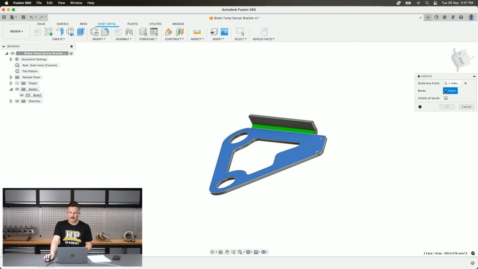
| 07:10 | This part here was a brake temperature sensor bracket so this was I think bolted to the bottom two fixings on the bottom of a coilover and then the little infrared brake temperature sensor was mounted here to these two mounting holes and that just basically pointed the brake temperature sensor at the rotor. |
| 07:40 | So this part was fine to be, it's a simple part and it was just made with a sketch which I'll open now. |
| 07:50 | Relatively simple sketch to match the brake temperature sensor and then an extrude and in this case it was simple enough that I just copied this onto a drawing, exported that as a DXF and then we just got this plasmacut at our local plasma cutter and then used that on the vehicle. |
| 08:17 | But in a case where it's not so simple, and we want to use bends and forms in our part, we need to convert this to a sheet metal body and I'll show you how to do that now. |
| 08:31 | So if we have already made, modelled the part like this, we've used an extrude which creates a solid model, then we can come up to our sheet metal toolbar, under the create tab here and we see we have this convert to sheet metal and this converts a solid body of uniform thickness to a sheet metal body. |
| 08:55 | So if we click that and then we can just choose the source which is just the body and that will detect the thickness so I've already had this set as a 3mm thick part and we can set the material that we want to use here and you'll see it has sheet metal rule and we'll come back to that in just a moment. |
| 09:19 | If we hit OK we can see that down in our timeline here we've converted it to sheet metal and we can see the body here is now a sheet metal body. |
| 09:29 | So from there we could choose to use, for example if this part needed a bend which it didn't but for this example we'll do that, we could sketch here, we can make a bend line across the part just like that and let's say we'll put a dimension on it to define it, 25mm. |
| 09:55 | And then jump back into here and go bend, we select the stationary side, so as the name implies that's just the side that's going to stay put and then the bend will be relative to that stationary side so we select the side and then we select the bend line here and we can apply the bend to that part so that if the, imagine the mounting tab was in, the mounting bolts were in a different plane, we'd need to bend the part to have it facing at our brake rotor. |
| 10:29 | And within the bend tool here we can change the angle which we can enter the value here or we can simply click this to move that around. |
| 10:40 | We can also flip the bend to go the other way but if we just leave that at 90° for now and then we can also change the start position for the bend so that means if the bend radius starts at the sketch bend line, we can change that from here so it's centred on the bend line or it finishes at the bend line, it's just changing where the bend is relative to that sketch line. |
| 11:10 | So usually you'd probably have it centred on that bend line. |
| 11:15 | And we'll come back to some of these other things in a moment with the use of some other tools. |
| 11:23 | So if I did that, now we just have our bent part like that. |
| 11:30 | And we, so that's one way of doing it. |
| 11:34 | We end up down here with, we've got five parts in our timeline so not too big a problem with a simple part like this but if you are modelling quite a complicated model with a lot of bends in it then something like this can add up if you're doing a whole assembly, you'll end up with maybe 100 or more things in your timeline where maybe you could have minimised that. |
| 12:00 | So I'll just back up a moment here, delete these last three. |
| 12:05 | So we're back where we started and I'll actually delete the extrude as well, so we just have this sketch which I'll turn on so it's visible. |
| 12:15 | And I'll show an alternative way to do this. |
| 12:18 | So in some cases we will have to create a solid model first and then convert that to a sheet metal body using the convert to sheet metal tool but the alternative in this case is I could have very easily just clicked the flange tool from up here or here and then selected the profile and then that will create basically the same thing. |
| 12:45 | We have a few options here on what side of that profile we want to create the material, if we want it to be centred, side one or side two and we can just work from there. |
| 12:58 | So now I don't need to use the convert to sheet metal thing 'cause it already is a sheet metal body so that's already one process that's taken out of it for us. |
| 13:10 | And given that I could actually modify this original sketch and I could add the bend line in here, do the same thing, set a dimension on that, 25 and then I could come straight back into here, bend that, show the sketch. |
| 13:37 | Click the other side, the stationary side needs to be the same as the side that the sketch is on and then I could have the same thing and that has just reduced that number of features from 5 to 3. |
| 13:54 | So not such a big deal on a part like this but if you were doing a big model and you're trying to work efficiently, it does matter 'cause it all adds up. |
| 14:03 | It's a lot more space, the model will run a lot slower and it just takes longer to do as well. |
| 14:08 | So it's a good way to do it so we'll just remove that last bend that we've done and look at a few other options that we have. |
| 14:17 | So before we move on, I'll just get into the sheet metal rules so you saw that in the flange tool before, when we were making it, the sheet metal rule popped up and we had the option to change that. |
| 14:30 | Sorry when we were doing the convert to sheet metal body thing. |
| 14:33 | If we come in here to our sheet metal rules, we also have them up here in our browser. |
| 14:38 | If we click that, this shows our sheet metal rules. |
| 14:41 | So we've got this set up at the moment as a steel part. thickness of 3mm and we could come in here and we could edit this and this is how we change the thickness, so if we wanted it to be 2mm thick, we can change that in our sheet metal rules. |
| 14:59 | If we had made the part with the extrude originally as a 3mm thick extrude and then we convert that to a sheet metal body, that will automatically get that 3mm thickness and create that as our sheet metal rule but this is just a way to come in and change it. |
| 15:18 | And you'll notice here the K factor that's written here, we're going to come back and talk about this later so don't worry about that for now. |
| 15:26 | But we can come in here and we can change things, change the thickness and do that. |
| 15:31 | And the importance of our sheet metal rules, these are quite critical to modelling sheet metal parts in Fusion 360 and what it does is it basically applies these rules automatically to the part, depending on its material and its thickness and it helps to automatically apply DFM considerations, so that's design for manufacture considerations like minimum bend radius and things like bend reliefs, so little cut outs to basically ensure that we don't design something that when we go to make it, when we go to bend the part, is going to rip, tear or fracture and basically be a weak part so it basically will automatically apply some good practices to follow, for example having, if we just jump back into here, the bend conditions under here, we have the bend radius set to equal our thickness so that is a common thing that we see working with sheet metal parts, we want to make the minimum internal bend radius, the minimum for that needs to be the same as the material thickness and if we do it thinner than that or smaller than that thickness, so for example if we had a 1mm internal bend radius, we could basically have a part that is going to, depending on the material, tear along that bend and be very weak. |
| 17:02 | So that's essentially what our bend rules are doing and if I make another flange on this, so this is moving on, another type of, another way we can use the flange tool. |
| 17:17 | I'll be able to show you some of those bend rules in practice and how we can work around them as well, should we want to. |
| 17:24 | So imagine this part, in this orientation how it was and let's say that in the vehicle there's a lot of vibration and the part is mounted to the mounting holes here and the sensor is vibrating side to side and maybe that's resulting in a lot of noise in our signal. |
| 17:46 | So one way of stiffening a part is to add a bend or form the part, this is why dimple dies are used for example, adding strength and structure to an otherwise flimsy sheet metal part. |
| 18:02 | And bends do the same thing so if we fold up a return along an edge, it goes a long way for stiffening the part because you're essentially adding depth to it at the same time. |
| 18:13 | So one way of using the flange tool is just to select it and click an edge like this and then we can drag that out. |
| 18:26 | And something like this is going to give us some nasty bend reliefs here which don't look so good but we can come into our settings here and change this. |
| 18:37 | So bend position, this is like what we saw in the bend tool before and we can change this to change where that bend starts relative to the bend line which in this case is that outer edge. |
| 18:48 | So if I put it as adjacent, that puts it right out on that edge and I can change the angle and the depth from here as well so if I keep that at 90°, keep the height which is the height of the flange, just our return along here as 10, that's that. |
| 19:11 | And we can change some other things in here as well like the edge so for example I could offset this edge, if it's going to let me click that, and pull that back, just to get it away from that hole. |
| 19:28 | So we can also flip from here, do a few other things with the flange tool. |
| 19:36 | But if we jump down here we see this override rules preference. |
| 19:42 | So if we select this, I'll just make this a little bit bigger, we see down here we can select bend override, bend relief override, two bend corner override, three bend corner override. |
| 19:55 | So these ones down the bottom, that is if we bend up two edges of the part which intersected, that might be useful to us there but we'll just stick with these for now. |
| 20:07 | So we can override our bend rules here and the bend radius as we discussed before is set to the material thickness. |
| 20:15 | So if we wanted to and we wanted to risk a tighter bend radius, we can do that and we'll see as we do that, our model updates and we can also make that bigger as well if we wanted to. |
| 20:33 | But we'll come back to discuss that in a moment, changing that away from the bend thickness, or just controlling that bend radius in a practical sense. |
| 20:46 | And then the bend relief, so we'll see at the moment here we have these square little bend reliefs and that basically allows the part to be bent up along that bend line without tearing the part. |
| 21:01 | But we can choose to override those as well and we can change the width and the depth of those little cut outs, or we can change the shape of them as well, the tear one gets rid of it completely in which case the part would likely tear when we went to bend it or it would deform, or we can change that to a nice little round one there like that as well, we can change the dimensions of that. |
| 21:27 | So that is another way to do that and that is another use for the flange tool. |
| 21:33 | The flange tool can also be used in a lot of other ways, we can create for example, out of sketch of a single line we can create a flange from that, contour flanges, other things like that and also the flange tool can be used now to make a lofted flange which is a little bit hard to explain but it's really good for creating ducts and things like that for airflow in the vehicle out of sheet metal parts but that and the other uses of the lofted flange are a little bit more advanced and something that we don't really need to look into today for our introductory look into this. |
| 22:18 | So from here, once we have our part how we want it, we'll move onto getting the part ready to be manufactured, so that's usually from a 2D cutting process like water jet or laser cutting for a part like this. |
| 22:37 | So there's a few ways that we can do this and it kind of depends a little bit as well on if you're using a free or paid version of Fusion 360. |
| 22:47 | I'm working on a paid version of Fusion 360 at the moment and I'll show you the way to do it on this 'cause it's kind of the easiest way. |
| 22:55 | If I come here and I go to create flat pattern then I can just choose the stationary face, being this one and hit OK and you see that just flattens the part and down here we have the centreline for the bend here and we also have the extents of the bend. |
| 23:12 | So that is just the area of material that would be included in that radius. |
| 23:18 | And we can come up here under bodies and we can choose to turn that off if we wanted to and then from here it would just be a matter of going under this export tab and clicking export flat pattern as DXF and then we can just send that straight to our local laser cutter and say hey can you cut this for me out of 2mm steel or aluminium or whatever we might want and that would all be to scale and we would be able to get the part cut very easily. |
| 23:49 | So that is one way of doing it there. |
| 23:53 | An alternative way, if we just finish that, because if you're working on the free version of Fusion 360, sometimes when you get to that point and you go to export the DXF, export the flat pattern as a DXF, it won't let you and that's kind of how they get you but there are some work arounds for that so one option would be if we've used the flange tool which created this return by adding the material, we can come back in here and we can choose unfold and that's basically just a way of creating a flat pattern. |
| 24:29 | We can click the stationary side and then the bend that we want to flatten and do that. |
| 24:35 | Then we can just simply sketch on top face and one way would be to project those lines onto our sketch and we can probably delete these two, or maybe not. |
| 24:53 | And then we can jump into here and we can come down here, right click the sketch and go save as DXF and that is available to do in the free version of Fusion 360 so that's one quick work around and that also shows you how to use the unfold tool and then if you wanted to refold it you can just come back here and click refold up the top and that will do that, we'll just hide that sketch again. |
| 25:21 | So a few simple ways of basically getting the part ready for manufacture. |
| 25:28 | So I'll just jump back to my notes and at this point if you have any questions specific to modelling sheet metal parts in Fusion 360 or possibly other CAD software, fire them in the chat and I'll do my best to answer them when I'm finished up in a moment. |
| 25:47 | So just a few other things to discuss. |
| 25:50 | We saw that K factor value in our bend rules earlier and some people might be wondering what that's all about and it does have a significant effect on our design so I've got an image here that I'll just bring up that kind of illustrates what the K factor is. |
| 26:11 | So if we bend the part like this, we have the neutral axis which runs down the middle of the thickness of the part and as it bends, the top is under compression here and the bottom is under tension so this compresses and this basically elongates and the K factor is just the ratio of the neutral axis thickness. |
| 26:33 | So where that is offset from the front of the part compared to the thickness of the part. |
| 26:39 | And why this is important is it allows us to understand how the length of the part will change through a bend. |
| 26:48 | So if we have 100mm long part and then we bend it, we're not right in the middle, we're not just going to have two parts that are, two flanges which are 50mm and 50mm, it's probably going to change and that's probably going to decrease slightly and the K factor allows us to understand that. |
| 27:09 | Luckily for us, the K factor is applied in Fusion 360's rule sets and it's factored into it so it's basically automatically applied for us and we don't need to worry about it but it is just something to understand. |
| 27:27 | So let's just talk about some of the limitations with modelling sheet metal parts in Fusion 360 and this isn't the same for every CAD program. |
| 27:36 | So if you're working in Solidworks for example, you will be able to use sheet metal forms and that is really helpful for modelling something like a dimple die which is used a lot in motorsport applications to stiffen an otherwise flimsy sheet metal part. |
| 27:55 | You can model it in Fusion 360 using some slightly more imaginative methods but it is not a proper model of what the part is and how it's formed whereas in something like Solidworks or Creo Parametric, Pro E, you would be able to model the dimple die and basically press that into the part and create it how it would be made in real life. |
| 28:23 | So that's just one of the limitations in Fusion 360 at the moment, if you're working with dimple dies, you kind of have to do a round about method of doing it, of modelling it to show it in your model, in saying that, you don't really need to model a dimple die or a form in your model, it is something that can just be applied in the manufacturing stage and not shown in the model, given you have your hole size correct for the dimple dies that you're using. |
| 28:58 | So moving on, that is probably the one main limitation I've seen, now that the rip feature has been added in, that kind of negates the other one I was going to talk about. |
| 29:10 | The other thing we need to consider is design for manufacturing and this is one of the common areas people kind of have a bit of an issue when they're modelling in general but especially with sheet metal parts. |
| 29:23 | It's very easy to model whatever you can think of in sheet metal in Fusion 360 or any CAD program for that matter and then when you get the part cut and then you go to make it, you have issues with making it how you had it on your screen. |
| 29:40 | And there's a few different ways this can show up. |
| 29:43 | One of the key ones is bending and I've just got a little bit of cardboard here that I'll do a little demo with. |
| 29:52 | Sometimes if we bend a part on Fusion 360, that's all good and well and then we go to our sheet metal folder on our workbench or maybe we're using a vice or something like that and we just can't create the bends how they were in Fusion 360. |
| 30:05 | One of those things comes back to our sheet metal rules and that is if we're using a special press to bend our part where we have dies and that will control the radius of the bend, that's all good and well and those sheet metal rules are great for controlling that and making sure that we've got it correct. |
| 30:27 | If we're just bending our part in the vice, we can't actually control the bend radius so everything we've done for our sheet metal rules around that bend radius is kind of negated and we're not going to be able to make a perfectly 3mm radius bend so that also throws out things like our K factor we were talking about before and changes the length of the flanges and things like that so it's just something that we need to think about in terms of tolerance in parts if we have holes on different edges of the flange, maybe we need to slot one of them to make sure that the part will still fit, things like that. |
| 31:11 | Other things to consider are whether we will actually be able to make the bends at all. |
| 31:15 | So with this piece of cardboard, you imagine if we were trying to make a part like that with a u shape but pretty long flanges quite close together, sometimes when we bend that one up and then we go to put it in our sheet metal folder here and bend again but we find that this edge hits the parts of the folder, that's a really common one to run into and just something that we need to think about while we're designing the part whether we can achieve those bends in that spacing at those angles and maybe our design needs to be changed a little bit if not. |
| 31:55 | The other one to consider around design for manufacturing, specifically with sheet metal parts not related to bending is the actual cutting process so if they're CNC cut on a laser cutter, water jet cutter or plasma cutter, all three of those methods have different DFM considerations. |
| 32:16 | What I mean around this is things like the size of the, the diameter of a hole cut though the certain thickness of the material for example. |
| 32:27 | A good rule of thumb for a plasma cutter is to use a minimum hole diameter of the material thickness, so if we've got a 10mm thick piece of steel and we want to cut a hole in it, the minimum diameter for that hole should be around 10mm and this changes for different plasma cutters and different materials but if we just roughly compare that to something like laser or water jet cutting, we can generally cut a much smaller hole, usually about half of that thickness. |
| 33:03 | So a 5mm hole for that example. |
| 33:06 | And then there's other things as well that come into it like how close we cut a hole to the edge of the part in plasma cutting, again it's generally a bit rougher so that hole needs to be further from the edge, otherwise we risk blowing through the edge of the part or basically after the part is done and we try to work with it, it'll crack through the hole to the edge of the part. |
| 33:31 | Again may or may not be a problem, depending on what you're designing but this is something that we want to cover in more detail in a coming webinar about the DFM considerations when you're designing parts for different manufacturing methods, be it sheet metal parts that are going to be 2D cut or things like milling, CNC mills or lathes as well. |
| 33:55 | So I'll just jump over to my notes and check some questions if there is any. |
| 34:12 | So Zue de los Sol, sorry if I butchered that, I probably did, can you do “reverse CAD” from a picture? You absolutely can. |
| 34:24 | I'll try to show you very quickly and example of doing that. |
| 34:31 | So in Fusion 360 here we have what's called a canvas and that's a very quick and easy way of doing that. |
| 34:42 | So, not sure what this is exactly, but we can apply that image to a plane and this is what you're talking about, a picture, this one is actually a 2D sscan from the scanner and we can calibrate this. |
| 35:07 | So I've scanned this along with a ruler to make this process really simple, so if I calibrate the distance from here to here, I know from the ruler that that should be 150mm and then this is the restrictor here, which I can't remember exactly what it was for, oil flow I'm assuming, and we can start to model based off that picture, so place the holes where they need to be, just doing this really roughly and then work around the outline of the part, however to make it work like that. |
| 35:55 | And you get the rough idea, sketch around the part and then we can design and copy that flange exactly from the photo with a bit more care than this obviously but that is a really good way of reverse engineering basically from a 2D image and we find that using flat bed office scanner is a really good way of doing that, obviously you've got to be very careful with the glass on it but that gives you a nice image with no distortion in it like you might get from a wide angle lens on a camera. |
| 36:28 | So that's a good way to do that. |
| 36:31 | Doesn't look like I have any other questions so I'll just wrap that up there and we'll be back next week with the next webinar and in the future, looking to cover some of those DFM considerations around using CAD as well for the different manufacturing methods. |
| 36:46 | So thanks for that, I'll see you next time. |


