338 | How to model Velocity Stacks in OnShape
Summary
Velocity Stacks (aka Intake Trumpets) keep the intake air flow smooth and even, reducing restrictions and increasing our power potential. Using a 3D model tailored to our requirements we can get these made via various CNC processes, like Machining or 3D printing. There's also a few different ways we can model them, so in this webinar we'll look at this process using OnShape as our CAD software.
| 00:00 | - Hey team, Connor here from HPA and welcome to this week's webinar. |
| 00:03 | This week we're going to be talking about modelling velocity stacks in OnShape so actually going to give you a demo of modelling velocity stacks or intake trumpets, air horns, whatever you want to call them, inside OnShape which is a free online browser based CAD software. |
| 00:24 | So velocity stacks, let's just start with that. |
| 00:27 | We'll just jump onto my computer here, I've got an image here of my personal intake setup. |
| 00:33 | This is a WhitleyTune sports injection kit from here in New Zealand for the L24 engine in my 240Z. |
| 00:41 | So velocity stacks, intake trumpets, whatever we want to call them, these parts here bolted to the throttle bodies and then we've got the manifold here so I won't get too deep, I won't get into the reason why we'd have these but it's essentially about keeping that airflow unrestricted on the way in, keeping the flow nice and smooth and laminar at high airflow velocities. |
| 01:10 | So that's why we have this kind of runner length and the nice bell shaped mouth on the end to keep that airflow smooth. |
| 01:19 | The length of them, these ones here are very long pieces, depends on the harmonics in the intake runners and there's a lot to do with that about tuning powerbands especially in naturally aspirated engines. |
| 01:35 | But we'll cover that in a separate thing, today we're focusing on CAD. |
| 01:40 | So why would we want to model our velocity stacks in CAD software? And we might just be doing it for a few different reasons, one of them might be just to have it inside an assembly, say we're trying to design something like this and we want to see how it'll fit and maybe how it would look if we're designing an air box, we might want to check clearance issues so that might be a reason. |
| 02:09 | The alternative one, and one of the key benefits of using CAD is the ability to use CAM which is computer aided manufacturing which basically is allowing us from our CAD software or using another CAM software, control CNC machine to make the part and that could be something like a 3D printer or a CNC machine like a 5 axis mill or a lathe or something like that. |
| 02:38 | So various different processes that we could use to make these, we'll just jump onto the overhead camera. |
| 02:45 | This is one of the velocity stacks here from that photo so this is anodised grey but this is an aluminium machined part here so that's one process of making something like this. |
| 02:59 | And the kind of form, geometry, thickness and obviously the length of these changes a lot for different engines but they're all generally the same kind of trumpet shape. |
| 03:12 | This is another example here of one off our CRX, Honda CRX racecar with the K20 engine and that uses Jenvey ITBs and this part here, the actual trumpet is a spun piece and then it presses into the bottom mounting plate and it's kind of bonded in down here as well so alternative method, or here this is the ones that we'll be running on the K20 in the CRX for the next season and these are designed to be sloped downwards, so allow us to not have a big hole in the bonnet basically, keep the whole intake under the bonnet because it sits quite high in the small EF Civic CRX engine bay. |
| 04:07 | So this actually is a 3D printed part, just basically in this case 3D printed out of PLA and this allowed us to check the clearance in the engine bay, design an air box around this and make sure it all clears under the bonnet. |
| 04:26 | So in this case just used for checking clearances but in saying that, this could still probably be run in the engine on the dyno if we had the bonnet open and a big fan pointed in for a limited about of time just for testing purposes, obviously we wouldn't run with PLA or some type of plastic filament like that out in an endurance race because it would clearly not hold up to it, melt and we could end up with parts of this in the engine which we clearly don't want. |
| 05:01 | But in saying that, doesn't mean that that's always the case for 3D printing. |
| 05:06 | More recently, the 3D printing of materials that can handle high temperatures is becoming more and more accessible so 3D printing from things like carbon or PEEK, things like that would allow us to 3D print a part like that and actually run it in a racecar and be subject to high temperatures but the 3D printing naturally lends itself to lower quantity, more custom runs of a product or a part and allows us to do testing so like I mentioned before about how the length of it affects the powerband so a good way to check what maybe is the ideal solution for the length and then we could go from there and get the part made or machined from a more suitable material after it is 3D printed. |
| 06:03 | So that's essentially why we would want to model a velocity stack in CAD so let's get into CAD and just start showing you how to do it. |
| 06:15 | So right here we're in OnShape, so OnShape is a nice free browser based CAD software. |
| 06:32 | It's also cloud based as well so you can see on here, I've used this a limited amount of times essentially but these are the other parts that I've designed in here, so this was actually, we did another webinar previously on an introduction to using OnShape and we modelled this rod end here for our Honda City racecar in there just to give a bit of a demonstration of how it would work. |
| 06:59 | But the great thing about it being browser based is we can access it from any computer at any time where we have internet and then that is obviously the downside as well. |
| 07:11 | I think you can work offline to some degree but generally you're going to need an internet connection and be on the web to be able to model parts using this as opposed to an application based program like Solidworks or in some cases Fusion 360 which is cloud based file storage but you can work offline because it's application based. |
| 07:37 | So if we just get started here, we'll go create a new document. |
| 07:42 | And I'm going to show you a few different processes of modelling a velocity stack cause there's a few different ways of doing it as with everything in CAD. |
| 07:55 | No way is right or wrong, some ways are just more efficient and have limitations but we'll discuss all of that as we go. |
| 08:03 | So the first way we're going to do it is using the loft tool as the primary means of creating the velocity stack shape. |
| 08:13 | So we'll start off and it'll be quite simple, we'll just sketch, choose the sketch on the top plane here and if we right click on the top plane we can view normal to that. |
| 08:27 | And then we can select the circle tool and click on the centre origin point there, drag this out and just make our circle. |
| 08:37 | And we will dimension that here and we'll make that circle match this part here, our CRX trumpet and the inside of that trumpet is 50mm at the base so using 50mm throttle bodies so match the ports on that there and then we can just finish the sketch. |
| 09:06 | So simple way to start, just sketch on the top plane with a 50mm circle. |
| 09:12 | So from here we're going to move on and we're going to basically sketch another circle higher up so first we need to make a new plane offset from this top plane so I just clicked the plane tool, set this to offset and clicked the top plane as reference and then we're basically choosing here how much higher up from that top plane we want to set the next circle. |
| 09:38 | So I'll take another measurement of how long the trumpet is and we are getting about 92mm to the top so I'm going to set this to 90 there and then it's the same process, I'm going to sketch on that new plane and I'll view normal to that as well. |
| 10:03 | Sketch another circle but this one's going to be much larger diameter so the diameter of this is actually going to be the outer diameter if we jump on the overhead camera here, of the trumpet and that is 100mm. |
| 10:22 | Just like that. |
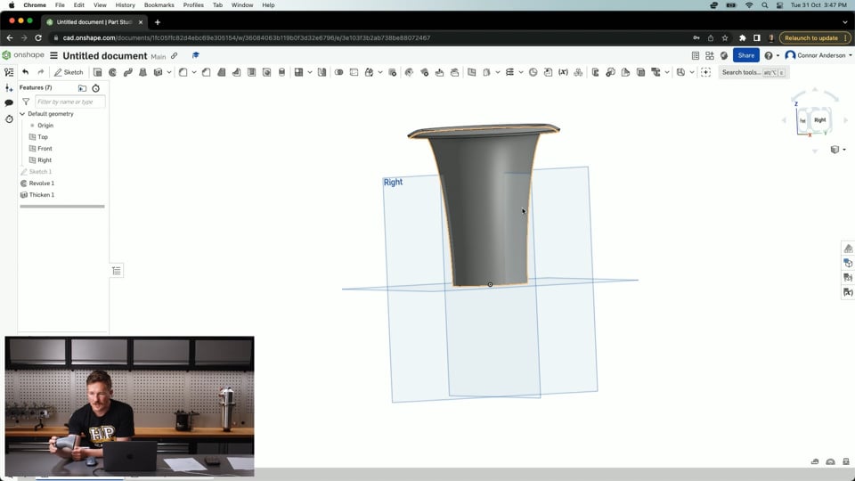
| 10:25 | So if we did a basic loft between those two, select the loft tool here and just select this profile, the bottom one and the top one, then that's the very simple cone shape that we can as a result. |
| 10:43 | We can make that with a solid or we can do it as a surface. |
| 10:50 | So if you're not familiar with what that means, a solid body basically has a thickness to it, so that would just be a solid cone shape and you could hollow that out afterwards whereas a surface, as the name suggests, it's an infinitely thin surface just the outer shape of that part so the reason that we would model something as a surface body is it is easier to model complex shapes. |
| 11:20 | So complex curves and things like that, it's easier to model it as a surface first and then add thickness to it later on so it can actually be manufactured and has a solid body to it. |
| 11:32 | So we'll work with surfaces for now and then we'll thicken that soon. |
| 11:39 | We can see the profiles we've selected here and then under here we can see the end conditions. |
| 11:45 | So this is the start profile condition and the end profile condition and basically what that means is sketch one is where it starts, the small circle sketch two is where it finishes and we have the condition at which the loft leaves that profile. |
| 12:01 | So if I change this to be normal to profile then we can see the loft extends out normal to that surface and then continues out from there and you could do it tangent as well would be the opposite. |
| 12:16 | Naturally it makes sense having it as normal and we can change that tangency weight so that's just essentially, or sorry the start magnitude it's called in OnShape and that is basically how long it's going to hold that normal to profile condition for so if I change that to two, you can see that it stays in that normal position for longer so that looks a little bit more suitable and then we have no condition on the other one but we could also change that to tangent to profile to give that a nice little lip there. |
| 12:57 | So that was already looking quite similar to this part here. |
| 13:02 | So we could very easily just finish that loft there and then it's just a matter of thickening this part so how we would do that is with the thicken tool, this one here, and we could just select that surface and add some thickness to it, so this part here's probably, 'cause it's spun, it's quite thin, it's only 1mm thick, we'll just make it 2mm and we can set that as the mid plane or add that thickness in either direction essentially there, let's say we wanted to do it like that, finish off, then we have this solid model here, hide the plane so it's a bit easier to see. |
| 13:54 | So that's a very basic way of creating a velocity stack there just using the loft tool, playing around a little bit with the settings and we're able to get that but, and then from there obviously we could sketch some more around the bottom and create the mounting surface, I'll give you a quick demonstration of how that might be done. |
| 14:20 | If we just make slightly bigger circle there we'll use, where's the use tool, just to use that edge as the profile. |
| 14:36 | Set that distance between, set that as say 60 and then we could add some more holes, doing this very quick and messy to match what the sample part I have here looks like. |
| 15:08 | Just making some lines tangent to the edges, I'll tidy this up in just a moment. |
| 15:21 | So if we use our constraints now, so constraints just allow us to essentially apply rules to our sketch features, looks like these are all already tangent. |
| 15:38 | And then from there I can use a construction line and if I connect those two and then I make the centre point here coincident with that, that'll mean they're in line directly across that and then I can make these two circles equal and also make that tangent there, that tangent there, set the diameter of those circles with the dimension tool, set that to 10. |
| 16:23 | Make some holes there, doesn't look like that's worked, tangent there. |
| 16:30 | And we'll just go with that for now and then we would just be able to click the extrude tool, select those profiles. |
| 16:46 | And make that just a few mm thick, say 3. |
| 16:53 | And then that's just a very very quick and rough way to make the mounting plate at the bottom of that there. |
| 17:01 | So that's essentially the same model as this, little bit rougher, without a few features but quickly enough, got that one done. |
| 17:12 | So I'm just going to mention the limitations of the process here so if we jump back up to just the surface of the loft here and zoom in, we're kind of limited by the shape of the end here so if we say look at this part here, we can see how this rolls over nicely here, that wouldn't be possible to create using this method where say the edge of this was further down than the top point. |
| 17:44 | So just show a slightly more involved way of creating the same thing so what I'm going to do is just delete these here 'cause we don't need them, and roll our bar back a little bit and I'm going to show the planes again and we're going to make some more sketches and construction planes. |
| 18:11 | So we have our two profiles here and we're still going to use those but we're going to create a new plane just slightly higher say 3mm higher than that top plane that we already have. |
| 18:27 | So now we have that, and same thing, I can sketch again on that, view normal to, just makes it a bit easier to line things up and make another circle there so now we just have 3 circles and let's say we'll make that, yeah 80mm. |
| 18:54 | So now we have 3 circles. |
| 18:56 | You might see where I'm going with this, if we just jump back to our loft and edit that loft, we can jump into the profiles here and select that third profile so you can see that this isn't what we're trying to do, this kind of looks like a bubble flare on the end of a brake line but I'm just going to reorder these and we'll see this won't generate but I'll show you how to fix that in just a moment. |
| 19:26 | So we're trying to loft between, this is the first profile, the small circle, then the next size circle which is higher up and then back to that but naturally that's not really going to want to work. |
| 19:38 | We'll just set these to none and we're still having some problems. |
| 19:43 | So we'll see down here in the options it says guides and continuity. |
| 19:49 | So, continuity sorry. |
| 19:53 | We can use these what's called guides to basically guide the shape of the surface when we make it so we'll jump in and we'll do that now and that's going to require the use of a few more sketches. |
| 20:06 | And if you're unfamiliar with modelling, generally we use a lot of sketches and that kind of builds the foundations, we create a 2D sketch, sometimes a 3D sketch and then we use these construction tools like the extrude tool, the loft tool, the revolve tool which we'll use soon to create 3D bodies from those 2D sketches. |
| 20:28 | So what we'll do is we'll just jump back behind the loft again and then we're going to sketch on the front plane this time. |
| 20:39 | And again I just want to view normal to that and then I'm going to use this use project tool here, or convert and basically what that does is that brings other elements into the sketch that we're using so we can reference them in the sketch. |
| 20:56 | So I'm just going to select those three there. |
| 21:04 | So then from here what I'm going to do is actually use the spline tool, so this basically makes a spline which is a bit of a complex curve shape, sorry I don't think I got those. |
| 21:20 | Now I have the reference, those three other sketches and then I'm going to use the spline tool to create a curve between those three points and just to finish this, if I press the escape button, that will do that and I'll just leave that as it is and do the same on the other side and I'll just keep it simple just like that and finish that sketch and then do the exact same thing but this time on the right plane. |
| 21:49 | So view normal to the right plane and project those three sketches in, hit enter to confirm that and then do a spline between those points, escape to finish the command, same thing. |
| 22:12 | So now we can kind of see with our sketches a bit of a wire frame model for the loft and if I just jump back into the loft and right click to edit, we can see we still have our profiles selected but we're going to come down here and click guides and continuity. |
| 22:33 | And for the guides we're going to select these new edges that we've made and we can see it's already been able to generate that. |
| 22:46 | And then finish that off and I'll just hide the planes to make it a bit easier to see and you can see that's allowed us to create this quite nice kind of bell mouth or return over on the top there. |
| 23:00 | So we could obviously spend a lot more time modifying those guides and moving the cirlces around and that gives us quite a lot of flexibility there to create this and then the same thing here, it's quite simple to just click the thicken tool, choose that, 2mm, having a bit of an issue there, that's fine and then thicken the part so now we have this 3D solid model. |
| 23:29 | So yeah that gives us quite a lot of flexibility. |
| 23:32 | So what I'll do from here is I'll just create another document. |
| 23:43 | Jump back to here, create document and we'll look at an alternative method of creating essentially the same thing. |
| 23:54 | Which could be considered a bit quicker because basically as you'll see in a moment, we use less sketches to create the same part. |
| 24:05 | So what we're going to do for starters is we're just going to sketch on the front plane or the right plane, it doesn't really matter. |
| 24:15 | Sorry jumped out of that. |
| 24:17 | Sketching on the front plane and we'll view normal to that and from here I'm just going to draw a straight line vertical from the origin point there, didn't do a very good job with that. |
| 24:35 | Straight up and this line here is essentially, it doesn't actually matter how long it is but that is going to be used just in a moment for the axis of revolution for the revolve. |
| 24:50 | In some cases in Fusion 360 I would have a default axis there already so I could use that, if you're familiar with Fusion 360 but for Onshape, I'm sure you could probably set that up but I don't. |
| 25:06 | Quick sketch fixes it and then from there I'm going to use the spline tool again, click the bottom here and just set a few points. |
| 25:17 | So kind of very similar shape to what we had earlier and what I'm going to start with is actually making this, this is kind of like a lever arm here which guides the shape of the spline as you can see and if I set this lever arm perpendicular with the bottom plane here that means that as the loft starts it comes perpendicular or normal to that bottom plane so it's a little bit like what we saw in our loft tool before but it's just doing it in this sketch. |
| 25:55 | And then if I dimension this here, because this is going to be a revolve, this would be half the diameter and this might seem a little bit abstract at the moment but 25, half of 30, it'll make a lot more sense as we go on. |
| 26:12 | This outer diameter here is going to be the top of the trumpet, oh I did that wrong, sorry, take my own advice, 50mm, half the diameter and then I'll also set that there as 40 to be half of 80 just as we did before and then set the top of this at 100mm long and I"m going to set this here just slightly higher at 102. |
| 26:45 | So that's essentially created what we had before if we thought about the guides that we used in a cross section view. |
| 26:53 | And I can finish that sketch. |
| 26:55 | So now we just have this sketch and from here we can choose the revolve tool and select the edge or sketch curve to revolve and we're in the surface settings so we can select a closed, sorry an open sketch profile and then we just select the revolve axis here and then that'll revolve that around there. |
| 27:21 | So as you can see, with that done, it's just taken one sketch and one revolve feature to be able to create the same part that before I think probably took I think 5 or 6 and then from here it's the same process to thicken that part by I think we did 2mm before and you end up with essentially the same thing and again you can go in there and play with the shape of that sketch to do whatever you want and then of course from here, make the mounting holes at the fixture plate at the bottom of that as well to get the same thing. |
| 28:08 | So I'll just make a mention here that the limitation for this process would be naturally the shape of the trumpet so it can only really be in one axis because you must create the revolve around a straight axis so if we think back to the part that we looked at earlier you might be thinking well how would you model this because this clearly isn't revolved around that central axis so using that method we wouldn't be able to model this part so we would be able to model this part using the original loft technique which I'll show you in just a moment and it's a little bit more complicated but first of all, I'll just make a little bit of a call for questions, if you have any questions relevant to today's topic, CAD or anything like that in general, feel free to drop them in the chat and I'll do my best to answer them after I've finished this next demonstration. |
| 29:12 | So I'll just delete those for a start and we'll start fresh. |
| 29:17 | So we're going to start with a very similar process that we did with he loft tool before and I'm going to start with a sketch on the top plane and look normal to that and sketch circle on the bottom here. |
| 29:32 | Just dimension that at 50mm, pretty close anyway. |
| 29:37 | And then from here, similar kind of thing where I'm going to also make offset plane 100mm above that top plane but this is where things change a little bit so again I'm going to sketch here on that new top plane but in this case what I'm actually going to do is just sketch a line straight across here. |
| 30:06 | So this line is actually going to serve a little bit of a different purpose in just a moment where it's actually going to be the kind of centreline for a slot that we're going to create to create this kind of oval shape for this so little bit of forward thinking in this case but it'll make a lot more sense in just a moment. |
| 30:35 | So how I need to set this line up is click and put a point on the mid point there just check that I've done that and then if I make this in horizontal, I know that this is a bit skewed, alignment with the top there so it's dead on that line and then I can set the width of this and I'll set the width of that to 50mm to match that circle and then I'm just going to offset this about 20mm off and finish that sketch there. |
| 31:18 | So that might seem a bit strange how that's been done but again it's all going to make sense in just a moment. |
| 31:24 | So now I'm going to choose to create another plane and this plane is going to be at an angle to this line and we'll set that angle at 10° and see how that looks. |
| 31:41 | Probably not quite enough, we'll try 20. |
| 31:46 | And that is the right orientation for that. |
| 31:49 | So now we have that angle which will kind of match the slope of that. |
| 31:56 | It's maybe not quite enough, we'll go back into that and edit that plane and give it just a little bit more, see what 30 looks like and then we can sketch on that plane and this time we're going to use the slot tool so we'll just jump into the search here and select slot and then we just select this line and that uses that as the width, centre to centre width for that slot is the length of that line so that's why that line mattered before, oh I lost that sorry, need to press enter when that's done. |
| 32:38 | And then I can change the dimension of that slot to be 50mm, oh we'll do it bigger, maybe 60. |
| 32:50 | So now we have that slot and that's going to be kind of the mouth of the trumpet. |
| 32:56 | And then from here we are going to kind of do a similar process as before where we create a third profile essentially and then we'll make some guides as well so we can control the surface of that part. |
| 33:15 | So the next step is just going to be creating an offset plane, that can be, oh no that was correct, offset from that and we'll just do this as 3mm. |
| 33:35 | And then we can choose to sketch on that plane and I'll view that plane straight on and then if we use the construction tool, so that's just making sure the lines are construction lines so essentially they're not going to form the actual process, it's just a easier way of copying some geometry here using the use and project function and we can copy that and we can see that that has just copied this profile onto the new plane as a dotted construction line so that line won't be able to be selected as a profile 'cause I don't actually want to use it so what I'll do is I'll just take that construction mode off and I'm going to use the offset function which I'm not so familiar with here, I'll just search that. |
| 34:34 | Offset and I can offset those construction lines there and bring those inside. |
| 34:50 | So I just basically copied the slot from the previous sketch to keep the same centreline and then offset that just inside and I can set that distance to say 8mm or something like that. |
| 35:08 | Just to copy that slot up onto the new plane and then that's done. |
| 35:13 | So from here the next step is going to be creating the guides for this so first of all I'll sketch on this front plane here 'cause this is the easy way of doing it and then I'm going to just sorry click to use those profiles and then use the spline tool to do a very similar thing as we did before. |
| 35:52 | And then same as before as well I'm going to kind of use these levers here to pull this into the shape I want and make those perpendicular to that bottom profile so as the loft leaves that surface, it's all about the same. |
| 36:08 | We'll finish that off and then this one's a little bit more difficult because we can't just sketch on the right plane, because as the right plane goes up, it's going to basically miss this top profile so what we need to do is just make a new plane here through three points and those three points will be essentially the ends of this line for the slot, the centrepoint here and that's made this plane four here go through the middle of that and then again I can sketch on that plane and click use on the slots. |
| 36:56 | And then the same thing to make our guides here. |
| 37:01 | Use the spline tool, to link everything up. |
| 37:14 | And we'll just leave that like that for simplicity for now and then we can jump into our loft tool finally. |
| 37:21 | First of all we want to select the profiles in the order that we want to use them in, just like that and you can see it's getting a bit confused with that but that's fine because that's what our guides are for so we're going to select those guides. |
| 37:48 | Doesn't seem to want to work. |
| 37:57 | Oh we've lost something. |
| 38:01 | Just start that fresh sorry one moment. |
| 38:31 | Still not quite happy with it so we'll see what we can do with these. |
| 38:38 | That's not going to work. |
| 38:42 | Finish that, we'll just jump back into the profiles and edit them a bit to see if that fixes it. |
| 38:51 | Bear with me a moment. |
| 39:28 | Alright that's not seaming to work, I'll just have to show another option here. |
| 39:36 | So I modelled this using the same method earlier but the dimensions that I used for some reason must have worked and the other profile didn't quite work so if we just jump in here we'll be able to see basically what's happened. |
| 39:57 | Don't know what's going on, there we go. |
| 40:00 | So, ah right OK, well it might have just deleted the other one so we can't go back to that. |
| 40:09 | So basically what's happened here is I didn't use that top profile for the profiles, I just have the two profiles here and then you can see the guide rails being used here to control the shape of it so there we go, didn't quite work out as planned but that's essentially how you'd create the same thing there so we have the two profiles and then we have the guide rails to control the shape of it but basically the main takeaway there is that the loft tool is able to create this part with the angled surface so you're able to basically loft from one profile to the other or you'd be able to do it with the sweep tool as well if you're familiar with that and sweep the profile along a surface but the loft tool allows us to change the cross sectional shape from the circle to the slot as we go and create that part there in our model. |
| 41:14 | Whereas the revolve function wouldn't allow us to do that because we need to revolve around a single straight axis. |
| 41:25 | Just a note on that, we have done an introduction to OnShape before in the past so in another webinar so you'd be able to view the previous webinars to see that as well and in the future we're going to do some more modelling demonstrations like these so some motorsport or automotive style parts modelling them inside OnShape, Fusion 360, Solidworks and probably some other programs as well, maybe FreeCAD or whatever we get recommendations or suggestions for. |
| 42:02 | So feel free to flick us a message if there's anything particular that you'd like covered and we'll do our best to get to that. |
| 42:09 | Thanks for watching and next week we will be back with an introduction to using FreeCAD so as the name suggests that is a free CAD software and we'll get into that next week. |
| 42:23 | Thanks for watching. |


