339 | Intro to FreeCAD
Summary
FreeCAD as the name applies is a free CAD program, and this naturally makes it an attractive option for new CAD users. In this webinar we'll take a look at FreeCAD, discuss how it compares to other offerings, take a tour of the software, and model a part for motorsport use.
| 00:00 | - Hey team, Connor here from HPA, welcome to this week's webinar. |
| 00:03 | So this week we're going to have a bit of an introductory look into FreeCAD which is a free CAD software program so we're going to do a bit of a look at how FreeCAD compares to other CAD offerings that are similar, available for free or relatively cheap and then we're also going to talk about how to get set up in FreeCAD to start with your CAD projects, do a bit of a tour of the software and finally we're just going to model something so you get a bit of a look at how it all works in a practical sense. |
| 00:38 | So first of all, FreeCAD, as the name implies it is a free CAD software package but it is application based so we actually download and install it on our computer, little bit like Fusion 360 or Solidworks and it also stores the files locally on your computer rather than being cloud based like Fusion 360 is or OnShape is which OnShape alternatively to being application based like this, would be browser based. |
| 01:12 | And it's available on Windows, Mac and Linux as well so it doesn't really matter what operating system you're using, what's important about it for us is it is a parametric modelling software, compared to the alternative of direct modelling software. |
| 01:31 | Parametric system allows us to control our models with parameters, being able to set dimensions and things like that better, which will be captured in a design history so we can come back and modify them. |
| 01:45 | We really just have a better control over the model, although it's not as flexible as working with a direct modelling software but a parametric system is what, parametric modelling software is what we want when we're doing a mechanical design, so designing for parts that we're going to get made and installed on our race cars. |
| 02:08 | So it is free but it is also open source and basically what that means to us is it's just a little bit less stable than the other programs which are basically produced by bigger software companies. |
| 02:25 | And it tends to be a little bit buggy compared to them and struggle a bit more when completing harder jobs like working with bigger assemblies or maybe solving something that's a little bit complex as well and since it's not a commercial software, there's not really any big provider standing behind it, there's no really formal technical support for it and the online community is also a little bit limited and all of this stuff does matter if you're struggling with something, you need to search up how to basically get the job done, sometimes it can be limiting in software like this where there's just not as many people using it basically. |
| 03:09 | In saying that, the other thing that I'd also say is compared to the other software that I am familiar with, Fusion 360, Solidworks or something like Creo Parametric, and more recently OnShape, I would say FreeCAD is by far the least user friendly and it's also the least similar to the other programs so generally with CAD programs they all work very similar. |
| 03:37 | There are some definite similarities to FreeCAD but it's definitely a bit of an outlier when it comes to a parametric modelling software compared to the other ones so the skills aren't quite as transferrable compared to something like Fusion 360 to Solidworks for example. |
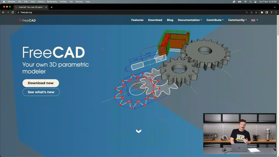
| 03:54 | So we'll just have a quick look at how to get set up and if we jump onto my laptop screen here, I just Googled FreeCAD and I'm on the website here. |
| 04:04 | And it's pretty simple, you can jump in here to download now or you can jump over to the download tab and then you can see here, that it is available for Windows, Mac and Linux. |
| 04:14 | And basically I'm using a Mac at the moment so we'd just jump in here, download the one that was suitable for our software and then it will come up and start downloading and then it's just a matter of following the usual method of installing it on your computer, you don't need to create an account or anything like that, it's very simple and straightforward and once installed you can just open the CAD software. |
| 04:42 | So I've got that open here, when you open it for the first time, this should be roughly what it looks like. |
| 04:49 | So this start page, basically just showing us if we have any previous files in here, it's got a few example files in here as well. |
| 05:01 | So we'll basically just get started with a bit of a tour of the software and then we'll move into modelling something soon. |
| 05:10 | So if we start, we'll just create a new document and then this becomes our model space, I'll just close that start page down the bottom. |
| 05:20 | So this is our model space, we've got nothing in here but it looks similar to Fusion 360, we've got our little icon up here showing our different views that we can rotate. |
| 05:32 | We also have a little coordinate system down the bottom right corner as well. |
| 05:38 | But probably what's the most important thing to set up first is if we go to this drop down list here, these are the different workbenches. |
| 05:46 | So a little bit like if you're familiar with Fusion 360 we have the different work spaces like design workspace, animation, computer aided manufacturing or also simulation, there's a few other ones as well. |
| 06:02 | This is a similar kind of thing here in FreeCAD where you can see we've got drawing here, part, part design and surface modelling as well, that's all in there but we also, additionally to this, it is possible to download, I assume because it's in open source software, it's possible to download what they call external workbenches so for example you won't see a sheet metal workbench in here but you can download an external workbench and I guess add it into here to use sheet metal modelling techniques but that just doesn't come with the standard download but it would still be free. |
| 06:52 | So additionally just diving in a little bit deeper here, we've got FEM here which finite element method, also known as FEA, finite element analysis, that's basically your structural, simulation, force simulation, stress simulation, the ability to subject a model to simulated real life loads and understand its response, some other important ones as well, the path one, where is that, down here, just under part, path would be the equivalent to computer aided manufacturing or CAM where we basically design our model and then we can jump in there and basically use computer aided manufacturing to create tool paths like G code to control CNC machines to make our part for us. |
| 07:55 | Other than that, it all looks like a pretty standard CAD software, we'll just jump back in there and select part design. |
| 08:03 | This is the main part where we would be doing, the main workbench rather where we would be doing our modelling for mechanical parts. |
| 08:13 | So if we're designing something for our cars, we'll probably be in the part design workspace, at least to start with to model it in the first place anyway. |
| 08:21 | After we've got that model, we'll move forward into the other workbenches perhaps to bring it to life. |
| 08:28 | So just moving left to right here over this side we've got things like create body and create sketch, we'll get into using these all in a moment and then these here are our datums so datum point, datum line, essentially an axes and our datum plane here as well so if you're not familiar with CAD we do use these datums, they're kind of like imaginary features to use as a reference to basically create the structure of our model. |
| 09:03 | Just jumping back a little bit as well, sketches here, we use 2D sketches, sometimes 3D sketches as well which, and then we create the 3D bodies from the sketches so that's generally how a modelling process goes. |
| 09:18 | 2D sketches, 3D bodies, in that process. |
| 09:23 | So just moving on a little bit, this is kind of one of the key differences here with FreeCAD, we have our additive tools here in the yellow and then in the blue and red here we have the subtractive tools. |
| 09:40 | So in something like Fusion 360 for example, you can use the same creation tools and basically inside that toolset, whether you want to add material or cut material, inside FreeCAD here, they've got it done a little bit differently where you just have different tools for adding material, creating stuff and then after you have that you can use these subtractive tools to take away from that, so cut holes in parts and things like that. |
| 10:10 | Past that we have mirror and pattern tools so once we have bodies we can use these to mirror things or replicate them in a pattern, just saves us a lot of time, makes things more efficient and then these are kind of like our modification tools over here so again once we have some 3D models, we can use these modification tools to round the corners or maybe add chamfers, add drafts, thickness, so yeah just to make a thick solid there. |
| 10:45 | So yeah a few different options and then some measurement tools along the end there and the bullion ones I think are things like being able to combine bodies or split them, things like that. |
| 11:00 | And then these are just the view options up the top. |
| 11:04 | And over on the left side of our screen here under combo view, all of this we can change by the way if we just jump up and change to view settings, change the toolbars that we have but over here we have our combo view and this has a little tasks tab which allows you to quickly create a new body which we'll do in a moment and then create a sketch similar to what we had up here or over here we have the model which is essentially the model tree so that would be the equivalent to our browser and timetime kind of merged together in Fusion 360 or just yeah the model tree in Solidworks is the same thing over here, we have our model tree. |
| 11:49 | So at this point I'll just make a quick call for questions if you have any questions related to this or any other CAD related questions after we get through the next process of just modelling something, I'll do my best to answer them as I go. |
| 12:04 | So let's get into modelling something. |
| 12:07 | If we just jump over here under the overhead camera. |
| 12:13 | What I have here is a rod end with a spherical bearing in it and then I also have two misalignment spaces here. |
| 12:26 | So these can kind of look a little bit different to this but they all serve the same purpose, essentially these can go in here and not hinder the misalignment or the angular misalignment capability of the rod end so say if this was on a suspension piece on the end of a suspension control arm or something, and then these here would be sandwiched between a double shear bracket for example. |
| 12:53 | So we basically, if we clamped the part between here, we have a small amount of misalignment that we can work with. |
| 13:03 | If we use a wider bracket then put these spacers in to take up that space, we can basically get more misalignment out of the part and then also we have a bigger surface area here to clamp between the bracket and we can put our hardware through the hole in the middle so in some cases this part here would also have a bigger lip on it here which would be called usually a high misalignment spacer and basically just allow for even more misalignment here but generally the bore through the middle of that is also narrowed up a little bit so you end up using a smaller bolt through it. |
| 13:50 | In this case you can see it's quite a thin lip there so the step down from the centre bore of the bearing onto the misalignment spacer is quite a small step down, you only lose a little bit of space to use a nice big strong bolt through there. |
| 14:08 | So rather than modelling the actual rod end itself, we'll just model one of these misalignment spacers, this would probably take quite a while, especially in FreeCAD. |
| 14:20 | So this is a pretty simple part and it lends itself quite nicely to using a revolve operation because essentially it's the same cross section revolved around the central axis which goes straight down the middle of the hole there so should be able to do that with one sketch and then one creation feature essentially. |
| 14:43 | So we'll jump back onto my computer and I'll just take a few measurements of the part as we go along to copy it exactly. |
| 14:52 | So if we jump back onto the tasks tab here in the combo view, start by creating a new body, we can see under the model here that we've created this new body which has an origin. |
| 15:06 | If we view that, that's not going to work, but that has its own origin in it and we can create multiple bodies here so we can work with multiple bodies in one design, essentially creating assemblies inside this workspace. |
| 15:27 | But within that body there we can then create a sketch, so we could do that from here or under the tasks but here as well. |
| 15:37 | Create a sketch and generally the same as every other program, when we open that sketch, we're prompted to start creating, choose a plane to sketch on so in this case we'll choose this XZ plane which could be called the front plane or right plane as well depending on the CAD software we use. |
| 15:58 | And now we're into our sketcher here, sketching workbench. |
| 16:04 | So from here we have different sketch tools along here like the line tool, arc, circle tool for example. |
| 16:15 | Then down the end here we have our constraints which we'll be using and the constraints are kind of like dimensions and it's one of the important things about FreeCAD is the dimensions are actually included in the constraints, more so in these ones here if I click this little drop down. |
| 16:34 | So the constraints, it's basically how we can constrain the sketch, so if we sketch a feature like a circle, then we control the diameter of that circle or the measurements from here and we can also align things and stuff and we always want to have the sketch fully constrained if we can to avoid unintentional errors creeping in. |
| 16:58 | But let's get started with sketching the cross section of this misalignment spacer. |
| 17:07 | So sometimes this can take a little bit of imagination but the more you do it the more you get used to it so kind of need to visualise the cross section of the spacer that's going to be revolved about the axis. |
| 17:19 | So if I just start sketching away here I can do this all with the line tool. |
| 17:24 | And it's going to look something like this. |
| 17:39 | This is one of the things with FreeCAD is how it snaps to points is not the nicest. |
| 17:49 | Is that going to let me delete that line, go back. |
| 17:56 | So you've just got to be careful to add the line to the end points, make sure it's all linked up because when we create the revolve in a moment we want to be working with a closed loop so all the points are together. |
| 18:13 | So from here we can see these small little dashes here actually are constraints that have been automatically added and these are vertical and horizontal, basically just showing that those lines are all vertical and horizontal and then these down here actually are coincident constraints, just showing that these bottom points are on that line so this bottom one basically doesn't need to be horizontal if they're both on that line which would be the XZ plane. |
| 18:48 | And over here, another thing about FreeCAD is it shows the, how the model is under constrained so it has these 6° of freedom here. |
| 19:01 | And basically, if I just deselect that line tool, we can come here and we can drag that and that's showing us the degrees of freedom that we have so the models not fixed, it can still move around essentially. |
| 19:16 | But we'll move onto adding some dimensions to this so this is best done under here so we'll just click that drop down here, if you have a bigger screen you might not need to do that and we can see here that we can constrain a vertical distance here so we'll choose that and we'll just select that line and this is going to automatically ask us to insert a length. |
| 19:41 | So this will be the height of our misalignment spacer here which we're getting about 19mm. |
| 19:54 | Add that in. |
| 19:56 | We'll just drag things around a bit to get this looking like it did before. |
| 20:04 | So when you're working with a revolve, we only need to sketch one side of the cross section essentially so if we cut down the middle of this part, we just need to sketch one side 'cause we can revole that around 360°. |
| 20:19 | If you're not familiar with CAD, that's going to make a lot more sense in a moment but what that means is we need to halve any diameter measurements 'cause we're only doing one side of it so if I do a, that there was a control, sorry constrain the horizontal dimension, so I can click this bottom point here, the origin point and this will be half of the internal diameter so that is 14mm or just over but that'll be an M14 anyway. |
| 20:58 | So 14/2, 7, I'll do that as 7.1 and then need to choose the next one, so I can do this top line with the same tool. |
| 21:13 | That will be that thickness there which is 8mm. |
| 21:26 | And you can see as the lines become fully constrained in this program, they will go green, if you're familiar with Fusion 360, they go from blue when they're unconstrained to black when they're fully constrained. |
| 21:43 | So we'll just add some more in here, another horizontal on this bottom line which is essentially just the thickness, wall thickness here which is only 1mm. |
| 22:04 | And we can do the height of that step. |
| 22:19 | So if you try to add a vertical dimension to a horizontal line that's not going to work so you'll just have to pick points, just a little bit more fiddly there, I could have just clicked that line I guess so that's the height there which is 9mm. |
| 22:45 | And then I could also do this line here with the right tool. |
| 22:54 | Horizontal tool on that line, just get that measurement would be about 2mm. |
| 23:05 | And we can see now that the sketch now is fully constrained so we can basically go from there and close the sketch, that one and now we just, if we look at our model view we can see under that body we have this sketch here but we'll jump straight into the revolution tool in this case and you can see it automatically creates that for us so just one thing to be aware of if I cancel that inside, it'll probably automatically do that 'cause we only have one sketch in this case in the body but generally in FreeCAD I find that you need to select the sketches first and then select the creation tool from there with them already selected, rather than open the tool and then select the sketches, it just works a little bit better than way so again if I select that it'll automatically revolve that profile around the vertical axis and we've got the angle here, 360° and if I bring that back a bit, you can see, controlling that, and then we just select OK and that's essentially it, if we rotate that, shift and right click on a Mac anyway, you can see how that's just created that part and it's just like the one we have here. |
| 24:36 | If we wanted to modify it to match the one here, see if I just clicked the chamfer tool there it says select an edge face or body so we actually have to select that edge we want to add the chamfer to first, select the chamfer tool and it adds that and then again I can control the size of that from there or type in the dimension that I want. |
| 24:58 | I think I could add other edges here as well if I wanted to and go OK so can add edges as you go. |
| 25:13 | But yeah so that's essentially a very basic model but a first look into using FreeCAD to model solid bodies anyway. |
| 25:24 | The key things to remember I think are around when you're doing the sketches, using the constraints to apply the dimensions, it's a little bit different to most other CAD programs where you just select the dimension tool and go from there and then just be careful when you're creating the parts, the create tools are split into those additive and subtractive things and sometimes you need to select the sketches or the features first to then use the tools. |
| 25:57 | But that is a basic view so if you wanted to get started playing around with some things, designing some parts in FreeCAD, you should be able to from there. |
| 26:07 | So I will just jump over, oh one more thing before we finish up. |
| 26:13 | If we wanted to add more bodies from this point, so we can see that body there in our model tree with the revolution there, with the sketch underneath it, the chamfer tool added, we could simply create a new body here or under the task here, we're already in a body so just jump into unnamed, we'd be able to do it under the task here as well to create another body so you can create multiple bodies in one part design file from there. |
| 26:49 | So I'll just jump over to the questions that we have, if we have any and see if I can answer them. |
| 27:06 | OK Richard Mashall, of the 4 paid CAD programs you mentioned, which is recommended? So I think I mentioned Solidworks, Creo Parametric or Pro E as it's now called as well as Fusion 360 and OnShape. |
| 27:26 | So what would I recommend, if you wanted to, I would recommend definitely starting with Fusion 360 just because there is a free version of it. |
| 27:36 | The free version you'll be able to do 99% of what you need to do for any automotive project and then if you find yourself needing more, those few extra features or a little bit more flexibility then you can just expand from there and it's relatively affordable at that point as well. |
| 27:57 | Also we obviously have our CAD course using Fusion 360 so there's no reason not to download the free version, follow along with the CAD course, learn in Fusion 360 and then you'll very easily be able to swap to any of those other CAD programs if you wanted to for any reason. |
| 28:17 | I wouldn't particularly recommend getting started with FreeCAD, it's just not quite so user friendly for beginners,. |
| 28:25 | You can definitely get a lot of functionality out of it and create some really poweful models but Fusion 360 is a lot more user friendly. |
| 28:35 | In saying that, something like Solidworks for example is kind of the industry standard, although something like Fusion 360 and Inventor are the other AutoCAD offerings getting more popular, Solidworks has kind of been the gold standard in this industry for a long time so it is a good one to learn with if you want to use it in a professional environment or you want to work for a company that uses Fusion 360. |
| 29:08 | Of course being able to use it already gives you a little bit of a head start and maybe that bit of extra edge you might need but any of them are great and if you start with one, just get started and then you'll be able to use all of them, promise you that. |
| 29:24 | Nathaniel Stephenson has said, is this essentially a Solidworks clone? Have to look into it, can't afford Solidworks. |
| 29:35 | No I don't think it's a Solidworks clone at all, it's quite different to Solidworks and Solidworks is in my opinion a lot better and just a lot more easy to use. |
| 29:47 | In that list I mentioned before I'd probably put Fusion 360 once you're familiar with it, at the top in terms of user-friendliness then Solidworks definitely next then maybe OnShape then Creo Parametric after that. |
| 30:02 | But of course there's 100s more CAD software out there that are all very good as well. |
| 30:07 | You say you can't afford Solidworks, I would just recommend looking into obviously the free versions of Fusion 360 or OnShape but I would also recommend looking into the Solidworks for Makers offering. |
| 30:24 | I think it's only about $100 USD a year so it is quite affordable and you basically get all of the functionality of what used to be $5000 to $10,000 for a Solidworks license so Solidworks for Makers is worth having a look at and that uses the 3D Experience cloud based file sharing system as well which can be beneficial if you are working with a team. |
| 30:57 | So that's it for questions, I just wanted to say we've also done an introductory look like this into Fusion 360, OnShape and Solidworks as I just discussed, in previous webinars. |
| 31:10 | So you'll be able to go back and have a look at those and see how it kind of compares. |
| 31:14 | And we're starting to look to do topics as well to show you for example, last week we did how to model a velocity stack or an intake air trumpet inside OnShape and we're going to do a bit more of that as well so if there's anything that I'd be able to model kind of within a webinar timeframe that you want to see done inside a particular CAD program, let us know and we'll do our best to get to that at some point but yeah stay tuned for some more CAD content in the coming weeks months and years. |
| 31:53 | So thank you for watching today's webinar and we'll see you next week. |


