341 | How to model Seat Brackets in SOLIDWORKS
Summary
Race seats come in all different sizes, and most brands use different mounting hole spacing. It's not uncommon for there to be no off-the-shelf bracket for your seat and chassis combo. In this webinar we'll show you how to model your own height-adjustable seat bracket in Solidworks using sheetmetal modeling techniques.
| 00:00 | - Hey team, Connor here from HPA and welcome to this week's webinar. |
| 00:03 | So this week we're going to be in Solidworks doing some CAD modelling and we're going to be looking at how to design sheet metal style seat brackets for the racing style bucket seats that have the side mount that are mostly used in motorsport applications. |
| 00:20 | So we're going to have a little discussion first as to why you might want to do this, what advantage this has for us modelling these in CAD and then we're going to move into actually modelling it in CAD in Solidworks and that's going to give you a bit of a insight into sheet metal modelling in Solidworks as well and then some kind of different approaches to using assemblies in Solidworks as well. |
| 00:44 | And then after that, going to also give you a bit of an insight into how you might design a similar part for your specific application, be that any seat that you're using in a particular chassis if it's not something that you can just purchase off the shelf for your applicaition. |
| 01:03 | So we've already covered an introduction to Solidworks using the Solidworks for Makers offering and the 3D Experience platform that Dassault Systems offers so that's what we're going to also be working in today but like I said, we've covered an introduction to that so if you'd like to look at that, you can head back to our previous webinars and check that out as well. |
| 01:27 | It's a little bit of an introduction look into this, if it's your first time looking at Solidworks, some things might look a bit different. |
| 01:35 | But we're also covering a lot of other CAD programs as well and things like this in different webinars and then of course our CAD course. |
| 01:47 | So first of all, why would we want to model seat brackets inside CAD? So first of all, I'll just show some examples, these are just ones that we had in the workshop, if we jump onto the overhead camera here, this is just a seat bracket that I found in the workshop, not sure off what seat but generally they are about a 3mm thick steel piece, this one is powder coated or painted and this one actually has kind of two bends here, a bit of a return and then the bottom flange. |
| 02:23 | So this side would mount to the seat and it's generally a pretty similar design for most seats, so this is off an OMP seat that came in the CRX that we're building. |
| 02:35 | Similar kind of design, holes on the side to mount to the seat, these are just for weight reduction I assume and it's basically the same thickness steel piece as well. |
| 02:47 | On my computer here I have a few photos that I took just before coming here of some other ones that we have in the workshop. |
| 02:58 | This one here is a very similar design again but this is actually about 5 or 6mm aluminium and you can see as it mounts to the bottom of the seat how it comes down here and mounts to this other bracket that would connect it to the chassis which has all these different holes in it so there's a lot of adjustability to be able to move the seat around. |
| 03:20 | And then this is another design here that Brandon actually designed in CAD and fabricated for use in the CRX whixh is a bit of a work in progress at the moment. |
| 03:31 | But you can see it kind of has these tubing rails across the chassis for extra strength and then these kind of brackets mounted to that which are a really strong design and then just a single sheet metal piece which mounts the seat there and he did a lot of work first to only have to use one kind of whole setup in this 'cause he knew exactly where it needed to be in the vehicle so we didn't really need the array of different holes down the side. |
| 04:02 | Just making things a little bit more simple and clean in that case but generally speaking, you'd be seeing something like this which has a lot of different holes for different applications and so you can move the seat, change the angle of it and the height of it and then you'd be able to move it back and forward on this bottom bracket as well for different people or if you just changed something about the vehicle and decide that you need to change where it is. |
| 04:30 | So being able to model this in CAD gives us a few key advantages. |
| 04:36 | One, it just gives us a visual understanding of what it would look like and if we can assemble that with the seat or 3D scan of the chassis or something as well then we can quickly understand our spatial constraints and if it's going to work or not. |
| 04:51 | But past this, it also allows us to manufacture the part a lot more simple. |
| 04:56 | There's a couple of methods we could use here, of course something like CNC laser cutting or something like that or we could simply print it out onto a piece of paper, make a template out of that and then cut it out of sheet metal ourself and make the part by normal fabrication methods. |
| 05:19 | But obviously if we have it in CAD then one of the main advantages is using CAM or computer aided manufacturing to use CNC machines to quickly make the part very accurately for us. |
| 05:31 | So get this part laser cut or even water jet cut would be a good option there. |
| 05:37 | So with that covered, we'll just get straight into modelling it. |
| 05:41 | So we'll jump into the screen here. |
| 05:44 | I'll just close that, make things more simple and here we have the 3D Experience platform. |
| 05:52 | And from this I've already opened Solidworks up but this is just kind of the base hub or the cloud based platform for file sharing and applications from Dassault Systems. |
| 06:06 | But I have Solidworks open here. |
| 06:09 | I actually have this model of the Racetech seat that we commonly use in a lot of our vehicles set up here and this is just a mesh. |
| 06:19 | So it's not a solid model, it's just a mesh made up of all these different surfaces just to give a rough representation of the seat 'cause that's all it's used for, we're not going to use this obviously for manufacturing or anything like that, it's just used as a reference for designing up the parts around so we're able to put this in a 3D scan of the interior of the CRX for example and work from there. |
| 06:45 | So all I've done is just opened this in Solidworks and created a surface here just on the side of it which is a pretty flat part and we'll use that in a moment but there's not much to this and you don't actually need something like this, I think we got this model from Racetech. |
| 07:07 | But you don't actually need something like this to do this work, it might just take a few more measurements, just understanding the width of the seat, the spacing between the holes and maybe the kind of shape of it, what type of angle you'd need, mocking it up in the car and taking some measurements you definitely don't need this but it'll give us a little bit of an extra edge in the modelling process today to show a few different methods as well. |
| 07:31 | So that is just set up as its own solid part model here, file. |
| 07:39 | And we'll be using that in an assembly and we'll be modelling inside an assembly today using a bit more of a top down approach like what you'd generally use inside Fusion 360 rather than bottom up approach which you'd often use in Solidworks where you'd model the brackets separately and then bring it together into an assembly with the seat. |
| 08:01 | So we'll just jump up here and we'll create a new assembly, click OK and then we'll get started and the first thing we'll do is we'll insert a component and we'll just choose that Racetech seat there and insert that in. |
| 08:19 | So the colours are a bit funny because it's a mesh with so many surfaces, I think it's just trying to simplify things. |
| 08:28 | You'll notice here this little F here and that means that that assembly in our browser is fixed so if I click float, now that's essentially not fixed anymore, I can't click and drag it unless I clicked the move component thing which is somewhere in there. |
| 08:47 | But this little dash here means it's basically free to move and what I prefer to do is just align this seat with our coordinate system so Brandon had this set up in his system using Z as the vertical one and I just generally model with Y as the vertical even though Z vertical is a bit better for tooling processes. |
| 09:09 | So what I'll generally do is click float there and I just want to align that with the coordinate system so I'm going to select the mates here which is like joints in Fusion 360 and the method here is basically locking down degrees of freedom one by one to essentially we can find the location of it in the 3 dimensions. |
| 09:30 | So an easy way to do this without making the planes visible is just to look at our browser which has moved over here into the model space and then we can click the assembly, the default front plane here, just going to orientate it like this. |
| 09:50 | Be like that, that kind of needs to be and then I'll want the plane that matches that for the seat, that'll be the front plane and then swap the direction of that around and finish that one and then just do the next one the same process so the top plane for the seat, top plane for the assembly is going to need to match to that, again I just need to flip that over and then the last one being the right plane there. |
| 10:23 | And the right plane for the seat. |
| 10:36 | I must have made a, oh sorry I did I made a mistake earlier so we'll do that to that plane there. |
| 10:45 | So there you go, that is locked down. |
| 10:48 | And then you can see that little dash that was up here has disappeared now so we basically just have that seat set up in our assembly and now this is where the things are going to change a little bit from my normal method where you'd create an assembly and keep inserting parts and using the mates to assemble them together. |
| 11:07 | We're actually going to go to this little drop down arrow here and click new part and that's just going to create this new part here which is fixed and we can leave that fixed as well because it'll, it's fixed to the coordinate system of the model which we want anyway so there's no point doing the same method again. |
| 11:29 | And we'll just click to confirm that and then this is the difference here where we can jump into edit component. |
| 11:37 | So if you're familiar with Fusion 360, this is just the same as doing an edit in place on an external component within an assembly file. |
| 11:47 | So that's all we're doing here, we've essentially got an external component and we're going into edit that component within our assembly. |
| 11:54 | So basically we can get started modelling our seat bracket using this scan or this mesh of the seat as a reference. |
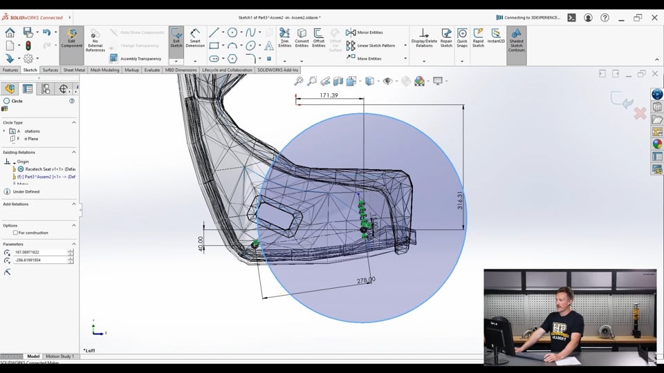
| 12:07 | So like any modelling process, we usually start with a sketch and we're just going to sketch on that side surface of the seat here so that's a nice flat surface which is where our seat bracket will mount to. |
| 12:22 | So we'll just get started here with first making some mounting holes around the bolts for the side of the seat here. |
| 12:31 | So typically these are M8 bolts that go into the side of the seat so we'll just start off with a circle there, placing it roughly in the right position and we'll just do this as a 9mm hole for example, that's just jumped out a little bit but that's no problem, can just drag that back into place. |
| 12:55 | And I've got no dimensions yet to show the position of this but I'm basically just going to put it right in the middle of that bolt hole like that and then we're going to use some other dimensions to the origin point here just to lock it down so it's not going to move, nothing weird's going to happen, doesn't particularly matter exactly the dimensions of what these are because it's all kind of arbitrary in space anyway and that just goes black to show that it's locked down. |
| 13:26 | From there, we're actually going to use, so the front hole is always going to be fixed with a circular hole so that kind of datums the position of the seat and locks it in place and then the rear hole, because of the difference in how it moves and everything, and to allow for a little bit of slack or tolerance in everything, we're going to do a slotted hole for that. |
| 13:49 | Give a bit more clearance as well. |
| 13:52 | So first of all, we will just do another circle and this will make a bit more sense in just a moment, but we'll make that a construction circle there. |
| 14:06 | And we'll just drag that roughly into the right position again and we can add a relationship here between these two. |
| 14:18 | So this is just like our constraints in Fusion 360. |
| 14:26 | So we've got those two arcs and we can just set them as equal so they're both of that equal 9mm diameter. |
| 14:33 | And then I'm going to put another line in here which may or may not be required just between the centre of those two. |
| 14:44 | And I know that the spacing of these, 'cause I've measured the seat, is 278, 'cause our mesh is scaled to the correct size, that's all correct anyway so the distance between those two is that measurement. |
| 15:03 | And then I'll just also lock down the position of that with another dimension, vertical or horizontal, doesn't really matter. |
| 15:16 | Just to get it in the right spot roughly there. |
| 15:22 | So moving on from that we're going to start creating the other holes, the other, we're going to do 5 holes just like some of the other photos we had there for the front and rear to give I guess 25 different positions that the seat could be tilted or installed in without even moving it back and forward so we'll start off here just by creating another line which is going to snap automatically to perpendicular with that line we just drew between the holes and for that one we'll just click that again, also make that a construction line, just 'cause we're not going to use that in the actual final profile. |
| 16:07 | The length of that doesn't so much matter for now, we're just going to use it as reference. |
| 16:12 | And then from here, we're going to select the pattern tool, a linear sketch pattern and the axis for this is going to be that line we just created and then the entity to pattern is going to be our circular hole here. |
| 16:31 | And then we can work with these here, so this is the number of entities of the pattern that we want. |
| 16:39 | So we're going to do 5 and then we can control the spacing here, I think 15mm will work pretty good. |
| 16:46 | So that's just copied that hole 5 times up in this direction. |
| 16:51 | And we can just click OK. |
| 16:53 | And one of the kind of issues I've found with Solidworks, there might be a setting to work around this but these holes, the spacing isn't locked in, the spacing of these holes in the pattern isn't locked in as a dimension so I find that you just need to add another dimension here and then that locks them all down. |
| 17:15 | They're shown as black being fully defined. |
| 17:18 | So basically we're going to create the holes over here in a bit of an arc and that arc is going to be taken from the centre hole here to basically make sure that any position that we put the seat in on those holes, it's going to fit no matter what and then it's going to be an arc of those slots patterned up here but it'll make a bit more sense in just a moment. |
| 17:44 | So we'll create another circle from this centre point here to make that arc and we'll just click out here, that circle is also going to be a construction circle and we can set that with the diameter as 2 times the 278 radius or the 278 spacing between the holes, so just 278 multiplied by 2 there and that gives us that. |
| 18:13 | So things are going to get a little bit trickier here but not too much, it'll all make sense in a moment. |
| 18:19 | We'll just select the line tool again and click the back hole there and then select the centre point for the circle. |
| 18:32 | There, that's drawn an arc for whatever reason, not too sure. |
| 18:41 | Straight line between the two and we'll make that a construction line as well. |
| 18:47 | So what we want to do is use the centre point straight slot tool here and then we're going to click on the intersection between the arc that we drew for the spacing from that centre circle and then we're going to have it aligned with that line we just drew from the bottom hole here up to that middle circle so if we click on that point, drag out here, then make that like that and then we're going to add a relationship between this circle or arc here, end of the slot and the original circle and we're just going to make those equal radius and then we can set the spacing here of the slot basically and we'll set that at 25mm but we'll check if that's big enough or not in a while and maybe we can even make it a bit smaller. |
| 19:49 | So from there, we're going to jump back into the circular sketch pattern tool rather than the linear one this time and we're going to select the centre point for the rotation which will be that middle point there, the centre of the circle and then for the entities to pattern, we're going to select that slot. |
| 20:14 | And that's just each line of the slot there, the two lines in the arcs as well. |
| 20:19 | And we're going to do the same thing where we're going to do 5 spacings, if I zoom out a bit you can see them around here in yellow but we just need to change the spacing here to basically space them in a much smaller thing so it's not around 360°, we'll just do about 3° and that lines up those slots like that. |
| 20:45 | We are going to get a bit of interference with the harness hole in the bottom of the seat here but it shouldn't be too much of a problem 'cause this will be the lower setting anyway. |
| 20:56 | The reason that I am doing it for the lowest one here is we basically want to design the bracket so if the seat is in the lowest position, it still clears the bottom of the bracket. |
| 21:09 | Again that's going to make a bit more sense as we progress through the model but anyway you can see here the yellow slots patterned up about that, around that arc and we can just select finish that, finish that off. |
| 21:28 | Again the spacing is a bit funny for these, we'll just leave it, it shouldn't be any issue I don't think, I'd be able to, oh I can drag them off. |
| 21:41 | Let me just undo that. |
| 21:46 | So to fix that I can probably add a relationship between that centre point and this here, making that coincident. |
| 21:56 | That's overconstrained it, see if I delete this. |
| 22:00 | Na we'll just leave it, it'll be fine. |
| 22:04 | There, so that is our mounting holes and the little check that I was talking about before to understand if the spacing is going to be correct, we'll just do that now. |
| 22:16 | So basically we know that the distance between the centre hole and any of these is going to be perfect so if we moved the seat between any of these and it was, sorry the front was mounted in the centre hole and we moved the rear mount between any of these different slots, we know it's going to be correct because the spacing between the holes is that 278 measurement and that is the radius of this arc here so that's no problem. |
| 22:51 | But if we just jump over to the evaluate tab here and select the measure tool, this is like our inspect ruler in Fusion 360, we can measure, so say if we had the front mounted in this hole up the top and we had the bottom mounted in that, that's obviously going to be as far apart as it can get. |
| 23:10 | So if we select the centre point for that hole and then select basically along the slot here we need to make sure that 278 spacing is within the range here so this black line here is 270 so 278 is greater than that and then if I do that again with the end of the slot, we get 295 so 278 is less than that so the 278 measurement is going to sit inside that range and just to be sure, if we had it in the opposite location we could do that there, 270 again and this should be very close, 295. |
| 24:05 | So again it's going to be fine, we can mount it in any spot and it's going to fit within that. |
| 24:10 | If we wanted to, we could probably reduce this value here significantly down to 15 or something like that to have a smaller slot in the seat but that'll take a bit of trial and error and doesn't necessarily need to be done for this example today. |
| 24:29 | So we'll just move on back to our sketch toolbar here and we'll sketch the outline of the bracket now that we have these mounting holes how we want them. |
| 24:40 | So this is going to depend on the angle of the seat. |
| 24:46 | If we look at the seat here, if you can imagine that inside a vehicle, that would be sitting pretty upright. |
| 24:52 | In some cases it might be leant forward a little bit more, you never know how the seat's going to actually mount to the chassis, that might introduce a few different factors as well but you can imagine if we moved each mounting hole into the higher slot in the higher hole, it would stay at the same level approximately and obviously we could tilt it forward by moving the back up or we could tilt it back by moving the front up or anything within that range. |
| 25:25 | So it's going to depend on the vehicle and you'd have to take some measurements of the chassis to make sure you got this correct but essentially the angle of the bottom of the bracket I'm going to do as a straight line across here and then I'm going to add a relationship between that line and the line connecting straight between the two mounting holes there. |
| 25:52 | Oh, click the centre point so just shift to select both of them and make those two parallel with each other and then to define the position of that line I'll just put a dimension in there and we just want to make sure that that's going to clear the bottom of the seat and probably give a little bit of space for some hardware as well. |
| 26:15 | So let's call that 85, will probably be pretty good. |
| 26:23 | And then the position of that line relative to where those holes are kind of sideways. |
| 26:30 | So if I click here on the mid point of the line and the mid point here of this line, and then I can basically do another relationship here between these two and make those perpendicular. |
| 26:50 | And apply that, that's fully defined that and I'm just going to, sorry make this one here a construction line so it's not included and then I could set the spacing of this bottom line here as well so that's essentially, if we just jump to the overhead camera, this will be the dimension down here so how wide or how long basically we want the seat bracket to be so in this case, I haven't actually taken a measurement of that, we'll just do what we think looks about right for the seat which I'd say is probably about where it is, we'll call it 380 so that bottom line is now fully defined. |
| 27:35 | And from here, we just basically want to make a pattern which will be the steel to come around here kind of in that shape like that. |
| 27:46 | So we'll start by just sketching a circle, hmm, I'll do it off maybe this one, the second hole like that. |
| 28:05 | And this can obviously be changed depending on what you want the seat to look like, there's a lot of room for your own style or what you want in here. |
| 28:17 | That was off that second one, we'll do a similar kind of thing off here. |
| 28:26 | Ah we'll make this one a little bit smaller, dimension, maybe 65 and then we can basically connect up the edges here. |
| 28:36 | So I'll have a short straight bit off each side here just as a bit of a return. |
| 28:48 | Add a relationship here between that and that. |
| 28:54 | That's perpendicular and also add one between that and that as equal length and I'll set the length of that to 30mm and then from there I can click the 3 point arc tool, or actually we'll change that, use the tangent arc so if we start that, it'll be tangent to this line which we want and come up here and I'll just click on that circle, we'll add a tangent constraint to that in just a moment and we'll do a similar thing over here. |
| 29:36 | So if I click this arc in this circle I can make them tangent and do a similar thing over here, make them tangent. |
| 29:50 | And these bits here aren't going to be fully defined because it's basically all based on the position of those slots. |
| 29:58 | So moving on, I'll do a similar thing here where I will make the line in the centre and then bring it up to each of these points so we can do that basically on that line we have already between those points and I can set that as a mid point here too on that line. |
| 30:26 | And then it's easy to just set the length of that line to be equally spaced about that mid point so we'll call it 100 and then we'll bring this up to here and another line from the other end here up to this one and again, if we select that, hold shift, select that, we can make that tangent and same thing on this side. |
| 31:01 | The final thing that I'm going to do here is just round these corners, so that's just throwing up an error there because we've put this dimension here as the length of that line but obviously we're kind of modifying that with using the fillets here so it's just going to throw up a bit of an error but nothing really to worry about. |
| 31:23 | So yeah there we have a sketch of the thing there and we can just trim out the unwanted areas inside that, oh clicked the wrong thing there, one moment, and click, oh, trim tool, clicking and dragging through the parts that we don't need. |
| 31:52 | Gets a little bit fiddly if the line has intersected a lot of features and you can see it's kind of shaded in there the inside of that closed profile, escape to jump out of that tool and then what we're going to do is we're actually going to use another feature in a moment to model the bottom flange of this where it would mount to the seat rail or whatever bracket we have mounting to the chassis. |
| 32:21 | So we can finish that sketch and we're still editing this part, jump into the sheet metal toolbar here and then we can select this base flange tab thing and this is like Fusion 360 if you are familiar with these things where you can make a base flange out of this and rather than extruding it and then converting it to sheet metal after that, if we just use the base flange here. |
| 32:53 | It's not happy with me for some reason. |
| 33:02 | Saying that there's open contours. |
| 33:08 | Which we know there's not because shaded sketch contours is selected. |
| 33:28 | The sketch has both open and closed contours. |
| 33:32 | OK we'll work around this, we will jump over to the feature tab and use an extrude. |
| 33:40 | Oh I see it's just interfering with the mesh of the seat I think. |
| 33:46 | So let's just hide that seat for a moment. |
| 33:57 | Hmm we're still editing the component, OK, not quite sure what's going on there. |
| 34:03 | But we can choose to extrude that and we'll extrude the direction that it's extruding in is fine and we'll set that as 3mm to do that and then we're going to have to do a convert to sheet metal thing here. |
| 34:23 | Clicking either face and then we'll set this thickness here to 3mm as well and we'll set this default radius, that's what this here is to 3mm so when we bend the part in a moment or create a flange, it's going to automatically apply that 3mm radius and I'll just make the seat visible again. |
| 34:49 | And there we have that on the side, wouldn't worry too much about this, it's just because the seat's not perfectly flat on the end, we could go back in and modify this a bit so it's not going to cause any issues but we'll just leave that for now. |
| 35:05 | So now if we want to add a, there's two different ways that we could basically do this bottom return, we could have sketched it, included it onto this, sketched a line across and created a bend to move it around there or we could use this end flange tool here and select that bottom edge and then basically drag it out like that and then we can set that to be 40mm or so and that has applied this default radius here of 3mm so we just set that to be equal to the thickness of the part which kind of the general rule of thumb when working with sheet metal to avoid too sharp a bend radius which would crack the part or cause fractures or just basically high stress concentrations and you can change a lot of other things here as well with the position of the flange and things like that but we're happy with that. |
| 36:13 | Yeah we'll leave that as it is, go OK. |
| 36:18 | So that's just now made that little flange down the bottom there and the final thing to do would be to create the slotted holes to mount it to the chassis here so we can do that pretty simply. |
| 36:34 | Still editing that component we'll jump back and we will first, I think if we go features, extruded boss and then sketch on that plane there, then we can use the centre point slot tool, and sketch a slot there, we'll set that. |
| 37:06 | Why would that dimension be driven. |
| 37:15 | We'll set the width of it first I guess. |
| 37:18 | 10mm and that'll be for M8 hardware as well, actually these are for M10 so 10.5, that's the radius, needs to be 5.25. |
| 37:37 | Then just need to position that on here, 15mm from the bottom edge and we'll put that in, yeah 20mm, hmm maybe not, maybe 17.5mm from that edge there. |
| 37:57 | And then we're going to use the linear sketch pattern, again for the axis we're going to select that edge, oh that edge there as the direction, so we're going to pattern this up the side there, entities to pattern will be the slot and then we can basically add those and we'll space them at, does 15mm look pretty good, yeah 15mm and we could space them, wrong button, 15mm, we can add them all the way up to the top there. |
| 38:48 | Take one off and then I'll just change this measurement slightly to say 15.1. |
| 39:00 | Bit more just to bring it up to be a bit more equal about that edge. |
| 39:08 | Maybe less. |
| 39:13 | And then it's just a matter of using this instances to skip one here because we definitely don't need a lot of these ones through the middle so let's say we just want, 1, 2, 3, 4, 5 on each side, we can remove these ones in the middle here, pretty simple. |
| 39:43 | So we've got 5 left on the top, that's 6, 5 there, linear pattern, finish that off, exit the sketch and then we were already in the extrude tool and we'll extrude that, we'll go through, up to surface and we'll select that top surface there. |
| 40:20 | Have I selected the wrong tool here, I think I have, one moment. |
| 40:27 | Exit sketch, so I've still got that sketch, features, extruded cut, sorry been using Fusion 360 too much. |
| 40:39 | Select that sketch again and then that is automatically doing it, up to surface, yeah and do that. |
| 40:53 | So that has cut those holes into the flanged surface there and then just one more thing to finish it off, we'll just fillet these sharp corners here, this one and this one. |
| 41:06 | Sharp edges rather, with full preview so we can see it. |
| 41:14 | Yeah 10mm radius should be enough. |
| 41:17 | So there we have that one. |
| 41:20 | We can finish the edit component there, be pretty happy with that model, we could obviously change this significantly depending on the different seat, add all sorts of different details in here or different holes that would allow it to be moved forward and back as well, it just depends on the application and how you want it to look but that's the basic idea of how you'd do that. |
| 41:44 | If we wanted to copy that onto the other side there, we go to this linear component pattern, one here, click the mirror components, for the mirror plane, that's going to be, the right plane here and then components to mirror being that new part we created. |
| 42:09 | And then we just jump over to this next tab here and then we want to change it to be this setting here to just basically copy that directly over to the other side and there we have that. |
| 42:25 | We can change these settings a little bit to make this a bit more visible. |
| 42:33 | So I'll just change this component here to be black and the same thing could be applied to the other side here as well, make that black. |
| 42:48 | So there is our finished seat brackets. |
| 42:53 | Obviously pretty simple design but should probably work but yeah we could improve that quite a bit if we spent a bit more time on it. |
| 43:00 | Just to finish this off, easy way to do this is to right click and select open on that part and this will bring that up and then down the bottom here you can see we have this flat pattern which is hidden. |
| 43:15 | If we right click on that and go to export to DXF or drawing we can export that, hit save and that is going to export our DXF here just like that and we can export that to our computer and send that directly to a laser cutter or even use Send Cut Send or something like that and we'll be able to get that part back and that'll be to the correct scale, shouldn't be any issues. |
| 43:45 | So I forgot to ask for questions earlier on but if anyone has any questions they'd like to quickly enter then into the chat now, I'll do my best to answer them. |
| 44:00 | And yeah I'll just jump over to that now on my screen. |
| 44:14 | So Tan Nguyen , how do you factor in how easy it is for the part to be manufactured in your design? So yeah we definitely think about that a lot, pretty much every part we design, especially if it's being manufactured manually on a lathe or a mill or something like that rather than CNC, or actually saying that, we do it with CNC as well, I'll talk about a manual method first. |
| 44:38 | We definitely always consider the design for manufacturing so if changing a feature is going to make something significantly more difficult or almost impossible or really expensive to make then we'll definitely try to change that feature to make it as easy as possible but it's always going to be a trade off between compromises of making the part look how we want it to look. |
| 45:05 | But also it's going to depend on yeah things like cost and obviously performance as well. |
| 45:14 | We don't want to just make something really easy to make if it's going to be a massive compromise in performance. |
| 45:20 | But definitely we do factor in the manufacturing process and that goes for CNC methods as well. |
| 45:26 | If I'm designing something and it's going to be made on a 5 axis CNC, that's going to be a lot more expensive and in some ways limiting with who is available to manufacture it and if I can change that design so it can be made on a 4 or even a 3 axis CNC mill and then maybe we just need to do some finishing processes to it ourself once we get it, that would definitely significantly reduce the cost. |
| 45:58 | In saying that, there's always going to be projects that are just going to require a certain type of manufacturing method and it just is what it is but always keep in mind that as an option. |
| 46:12 | Monique Leveston, hey HPA are there plans for tutorials on designing parts based off 3D scans and working with meshes in Fusion 360 and Solidworks? Yes definitely, we have a worked example going out for our CAD course, it might already be up for the valve cover on our SR86 and we use 3D scans in that, specifically in that worked example we just used 3D scans taken off an iPhone basically, or any smartphone would work for that. |
| 46:52 | And we also have another one in the future which is the chromoly tubular subframe in our CRX racecar that was all done based off 3D scans as well using our Peel 2S 3D scanner and that's not to say that you'd have to have that scanner to make one of those parts, you definitely don't, it obviously just helps and we are going to do a lot more work in the future with 3D scanning as well. |
| 47:25 | There is a previous webinar I did where I scanned the Skunk Racing magnesium valve cover for our K20 that we got, just to show basically using our Peel 2S scanner and how simple it can be to scan and I compared in that webinar a scan from an iPhone as well. |
| 47:47 | So bit of an introduction look into 3D scanning and how that's used in Fusion 360 as well but we'll be doing more of that in the future. |
| 47:58 | I'm just getting a note here from Jordi saying that the worked example is already up or that course for the SR86 billet valve cover using those 3D scans so that worked example is up with our CAD course at the moment. |
| 48:12 | Initial DIY Mods says came in a bit late but did you go over load analysis, material selection, or justification for thickness selection, typical practice based on experience etc? So we didn't talk so much about that in this one, we definitely took the kind of approach to it in this one of we've got multiple examples here made of 3mm steel and we'd just copy a very similar design. |
| 48:44 | We know these are proven parts that work fine. |
| 48:47 | In saying that, definitely possible to do some type of FEA on it or stress test them in a practical situation by ourself as well and it is worth considering as well. |
| 49:01 | The photos that I showed at the start showed the difference in an aluminium version of a seat bracket and that was a significantly thicker material used there compared to the steel ones just because of the obvious difference in strength, steel being I think about 4 times more, 3-4 times stronger than aluminium, don't quote me on that but about the same so 3mm steel is often used but yeah with aluminium you'd typically see something north of 5mm used. |
| 49:38 | The design is definitely going to factor into that as well so it's something that you need to keep in mind if you just make lightweight holes all the way through it so it looks like swiss cheese, that's going to have a significant effect on the stiffness and the strength of the final part. |
| 49:57 | We didn't cover that so much in this but definitely something to keep in mind. |
| 50:02 | That is the last of the questions now so I'll wrap it up here. |
| 50:06 | We have covered other topics like this in the past for Fusion 360, OnShape and we're going to do more in Solidworks as well and we also have introductory webinars into looking at Fusion 360, OnShape, Solidworks and also FreeCAD, I think that's the complete list at the moment. |
| 50:28 | We are going to do more in the future so if there's anything you want us to cover, any ideas about simple things that we could model inside a webinar timeframe, please let us know and we'll do our best to cover them in the future. |
| 50:40 | Otherwise, I'll leave it at that, thanks for watching and we'll see you next week. |


