342 | 4G63 Solid Lifter Conversion
Summary
The 4G63 engine utilises a hydraulic lifter assembly that can be problematic in race or drag applications. In this webinar we’ll cover off the limitations of the hydraulic lifter and what’s involved in converting to a solid lifter arrangement.
| 00:00 | - So first of all, let's talk about what a lifter is and what a solid lifter is and what the alternatives are. |
| 00:08 | So what we're talking about here is our valve train and if we jump across to my laptop screen, figured it was probably easier to show you with a picture. |
| 00:17 | This is a photo from inside the cylinder head on our Mitsubishi Evo 9 4G63. |
| 00:24 | But essentially all the generations of 4G63 very similar, what we've got here is our cam lobe, this is the intake cam. |
| 00:33 | We've got the roller rocker mechanism here and what we can see is basically there's a roller that the cam lobe wipes across. |
| 00:42 | Down here the other end of the rocker assembly locates on the top of the valve so that actuates the valve and at this end which is the bit that we're interested in, this is the pivot that the roller rocker sits ontop of so basically this is where our hydraulic lifter is, the hydraulic lifter is designed so that it is pumped up using engine oil pressure and takes up any lash or clearance or gap if you like that would occur right in this spot here so that's how Mitsubishi do it, Before we get into some of the pros and cons of the technique that Mitsubishi use, let's talk about the alternative which would be a solid lifter. |
| 01:28 | This is probably how the majority of older engines did this, there's a variety of different ways of doing it but basically rather than using hydraulic engine oil pressure, we have a mechanical adjustable mechanism in there that we can use to adjust the amount of clearance between, in this case if we come back to my little picture on my laptop here, between that roller and the cam lobe. |
| 01:55 | There are some fundamental differences between the cam lobe designs as well between a solid and a hydraulic lifter which I'll get into in a moment, that is quite important to understand. |
| 02:06 | So the advantage here with a mechanical or solid lifter arrangement is that as its name implies, it's solid, it's not going to move and that's an advantage, particularly with a race engine that we're using at very high RPM. |
| 02:25 | Essentially we know what we've got, it's not going to move around. |
| 02:29 | Well kind of, it is actually going to move around over time. |
| 02:34 | Basically as the engine wears, what we find is that with a mechanical lifter arrangement or mechanical valve train we will find that over time everything wears and we need to go through and adjust our lash clearance. |
| 02:49 | That lash clearance again the term I'm using is that clearance between in our case the rocker assembly and the cam lobe but again there's a multitude of different valve train designs but essentially the same concept works across all of them. |
| 03:04 | So for a production road car this is not something that makes a lot of sense, particularly as our engines have become more complex, it'd be quite a time consuming process to have to take the engine or the car I should say, back to a dealership every 6-12 months and have them go through and adjust the valve lash on every single valve. |
| 03:26 | And that's obviously going to end up costing as well. |
| 03:28 | The other aspect here in terms of NVH which stands for noise vibration and harshness which OE manufacturers care about deeply for road cars, is that a mechanical valve train or solid valve train does tend to be a little bit noisier which obviously no one wants. |
| 03:47 | So the alternative here is the way Mitsubishi went about this which is the hydraulic lifter and we'll jump across to our overhead camera, I'll just get this somewhere in the centre, try work backwards here, so this is basically the entire hydraulic lash adjuster that we could see in that photo although in our photo we could obviously only see just this little top bit that sticks out. |
| 04:11 | So the idea behind the hydraulic lash asdjuster is that there are galleries in the cylinder head that provide oil flow to that lash adjuster, we should be able to just see here on the side of it, we do have a little hole, might be a little bit tricky to see with the light, there's a little hole there, allows our oil flow in. |
| 04:29 | And there's a check valve inside of it and I don't really need to get too much into the weeds with the internal design of it but basically allows pressurised engine oil in there and that will pump up that lifter and then that will take up that lash clearance and means that we essentially run with zero lash, with a hydraulic valve train, the rocker assembly, in our case with the 4G63 cylinder head, always runs against the lobe of the cam so even when it's on the base circle, it will be contacting the base circle of the cam. |
| 05:04 | Conversely with a solid lash adjuster or solid valve train we do need some clearance between the, in our case the roller rocker and the base circle of the cam which is when the valve is closed and I'll talk a little bit more about that soon. |
| 05:20 | So advantages as far as OE production cars go is that the hydraulic lash adjuster is almost for all intents and purposes maintenance free, it's going to adjust over time for any wear in the valve train, always maintaining that zero lash clearance, contacting the base circle of the cam, nice and quiet in operation and basically maintenance free, well that's the theory and for the most part, that is pretty well how these work out. |
| 05:51 | Mitsubishi is well known with their 4G63s or any of their engines that use these hydraulic lash adjusters that with high mileage, particularly if they haven't been well maintained in terms of oil changes, they do start to get a little bit noisy, probably most people in the Mitsubishi world would have either owned or experienced a 4G63 with ticking lifters and what's happening there is essentially the little lash adjuster is not staying pumped up and it's allowing it to move up and down a little bit, this gives us positive clearance that we shouldn't have with a hydraulic valve train and then we're hearing that ticking which is where the roller rocker starts to contact the cam lobe and then come off it again so a pretty sort of annoying sound, particularly for a road car. |
| 06:43 | We're not really getting into that side of things though because the reality is that while yes that is a problem, it can be very simply solved, there's a bunch of options for aftermarket lifters that will fix that or just brand new OE lifters which will be more money so we can fix that and if the engine is well maintained, this really isn't a common issue or a maintenance issue, however, for some very niche applications, and I did mention this is a niche webinar, for some niche applications such as drag racing, there are some problems with the hydraulic lifter. |
| 07:18 | In general, and I'm not talking here about the 4G63 but in general hydraulic lash adjusters are known to be potentially problematic when we're running the engines to much higher RPM than stock. |
| 07:31 | And the reason for this is that the oil flow provided to them at a very very high RPM can sort of overwhelm the internal mechanism and cause them to pump up so now not only do they take up the lash clearance, they actually pump up further and this actually holds the valve off the seat so obviously when that happens we lose all of our compression so don't need to be a rocket scientist to figure out that that's not going to be great for our engine performance. |
| 07:58 | The 4G63 didn't really suffer from this particular problem. |
| 08:04 | However what I found in drag racing was that they were really really problematic with a 2 step launch control strategy. |
| 08:13 | So for those who don't know what a 2 step launch control strategy is, basically it's a secondary rev limiter that we use when we're staging at the start line of the drag strip. |
| 08:21 | Typically it'll be run off a clutch switch, so when we've got the clutch to the floor, that will bring in our secondary rev limiter so now we can go straight to full throttle and instead of 10,000 or 11,000 RPM rev limiter, we might want to launch with 6500 or 7000 RPM for example. |
| 08:40 | Be one of the parameters that we're actually adjusting run to run as the track evolves to try and optimise the launch and the 60 foot performance of the vehicle. |
| 08:50 | So the secondary rev limit is one element of it but particularly as our turbochargers get bigger, we find that 6500 or 7000 RPM alone just banging away on the rev limiter is not actually enough to provide energy to the turbo to spool it up and with these really bit turbos we're going to actually need to create a reasonable amount of positive boost pressure in order to get the engine to have enough torque to leap the line cleanly. |
| 09:20 | So this is where using ignition retard comes in. |
| 09:24 | What we're going to be doing typically with these 2 step limiters is it will be an ignition cut limiter, so that means that in order to control the engine RPM we're randomly cutting spark to individual cylinders. |
| 09:36 | Nothing particularly unusual there but then when we do have an ignition event occur we're also retarding the ignition timing so maybe under typical conditions we might have 20° of ignition timing at 6500 RPM, instead we'd actually retard that maybe back to top dead centre or even after top dead centre. |
| 09:57 | Now the effect of that is for those cylinders that are still firing while we're on the 2 step, the ignition event's happening so late in the engine cycle now that it essentially continues into the exhaust stroke, so once the exhaust valve is open and the combustion event basically exits and goes out into the exhaust system. |
| 10:15 | There it also is combined with the unburned fuel and air that's coming from the cylinders where the ignition cut event has occurred. |
| 10:24 | So what we're getting now is explosions of this unburned fuel and air occurring in the exhaust system and as you could probably imagine, what this does is it creates large sharp spikes in the pressure in the exhaust system. |
| 10:38 | Great because this really helps to spool our turbocharger so it's not hard to make a turbocharger that otherwise wouldn't see full boost until 7500 or 8000 RPM still produce 20 psi of boost at 6500 RPM while the car's stationary on the 2 step limiter. |
| 10:55 | We can control the amount of boost that we're making by how much ignition retard we're using. |
| 11:00 | The more retard we use, the more energy is provided to the turbocharger and the more boost pressure we can produce. |
| 11:08 | The problem is though these sharp pressure spikes tend to pop the exhaust valves back off their seat and that's not necessarily going to cause damage in and of itself, I know it sounds a little bit scary, it's only probably opening the valve maybe a few thousandths of an inch is actually enough to do it so it doesn't have to be a lot, we're not in danger of popping the valve back off the seat enough that it's going to slam into the crown of the piston but just a small amount of opening is enough to then allow the hydraulic lash adjuster to expand, I'll just grab these bits here and show them, we'll get into this in a bit more detail, sorry I'm trying to work backwards here which isn't very easy. |
| 11:49 | Let's just bring this, there we go. |
| 11:53 | So this is the internal plunger mechanism here and this sits inside our lash adjuster and basically what will happen is the oil pressure will force this up to take up that lash but when the valve pops off the seat that then allows the lash adjuster to expand outwards and take up what is then deemed to be some lash clearance so the problem with this is when the lash adjuster expands like that and takes up that movement when the valve pops back off its seat, then it holds the valve open so the valve can't seat properly, again we get into the situation where we lose compression and basically the engine will probably sound like it's running on 1 or 2 cylinders, if we try and launch it'll just fall flat on its face and bog so we need a way of stopping that from happening which is where the solid conversion comes in. |
| 12:47 | So that's the main issue as I found it was the compatibility around using an aggressive 2 step limiter so again, I know it's niche, this really only becomes a problem for drag racing and even then I found it wasn't a problem with my own car and my customers' cars up to the point where we rarely stepped up to these really large framed turbochargers that needed a lot of ignition retard in order to create that exhaust gas energy and spool them so if you've got a factory turbocharger or even a mild or moderate upgrade turbocharger, this probably isn't going to be an issue, as we're going to see there's quite a bit of work involved with this so it's certainly not something that you would do without the need for it. |
| 13:33 | So first of all, let's just talk about cam profiles, so we'll jump across to my laptop screen, I'm not going to go too deep into this but it is really important to understand the cam profile and how that is compatible with solid or hydraulic lifters. |
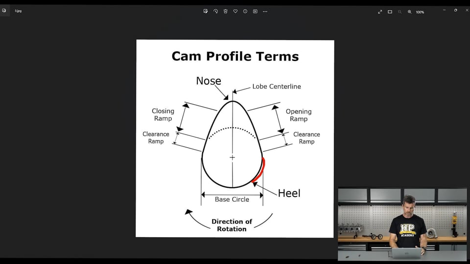
| 13:49 | So most people overlook this part, the hydraulic cam profile and the solid cam profile are quite different, particularly in terms of these areas here which is listed as our clearance ramp. |
| 14:01 | So with a solid lifter cam, what we end up with as I've mentioned is around this base circle here or the heel of the camshaft, we have a little bit of clearance between the cam lobe or base circle, heel, and our roller rocker so this might be somewhere in the region of maybe 6000 to 10,000ths of an inch so it's not a lot but it is some positive clearance. |
| 14:29 | Problem with that is that as the cam turns around, the lobe comes around and wants to start opening the valve, what we need to do is take up that clearance and that's done here with this little clearance ramp. |
| 14:41 | So basically it very smoothly closes up that clearance before it starts to actually lift the valve off its seat and we get exactly the same thing on the closing side, basically we gently or the cam gently closes the valve down and then reintroduces that lash clearance. |
| 15:01 | That's quite different to a hydraulic cam profile because with the hydraulic cam profile, of course that roller rocker is contacting the heel the whole way around here so there is no need to basically bring that clearance in or remove that clearance smoothly with the clearance ramps on both sides of the cam. |
| 15:22 | So the issue with this is that if we take a factory or aftermarket cam that's designed for a hydraulic lifter and we try and run this with a solid lifter arrangement and we use a typical solid lifter clearance, we're going to end up very harshly opening and closing that valve, it's going to be very very hard on the valve train, probably hard on all of our components and generally just isn't going to work for a long period of time. |
| 15:51 | That's not to say it's impossible, I have in a pinch where we had no option, run a hydraulic cam profile with a solid lifter but what it requires us to do is set the valve lash very very tight, in the range of 1000 to 3000ths of an inch. |
| 16:09 | So definitely not recommended, if you're going about this, what you would do is you would order a suitable cam that is ground for a solid operation and then that will have the desired clearance built into it so your cam card will tell you what your lash clearance should be. |
| 16:28 | Let me just go back to my notes for a second here. |
| 16:34 | Just to see what that looks like, if we jump across to my laptop screen for a moment, this is a cam card which is pretty typical of what they look like, this one is from Kelford Cams and just to be a little bit confusing here, this is actually for a Honda but Honda does use a mechanical or solid profile anyway. |
| 16:55 | The reason I just wanted to use this was to show this is here the recommended clearance on the intake, 0.3mm and that is set with the engine at running temperature at the valve, same on the exhaust so that's the sort of specifications you're going to find on a cam card when you are setting your valve lash or valve clearance, it will tell you where that measurement's taken, on the 4G63, that's between the roller rocker and the heel of the cam lobe and generally it's actually done cold on the Mitsubishi but there's a little bit more involved to actually make adjustments to our lash so that's probably why doing it hot wouldn't make a huge amount of sense. |
| 17:37 | So how do we go about a solid conversion? How do we actually do this? Well there's a couple of options. |
| 17:46 | Let me just, there we go, fine, this is an aftermarket off the shelf solid lash adjuster or solid lifter conversion kit which on face value seems like the perfect solution. |
| 18:01 | There's a lot of good design cues with this as well so looking at each one individually, basically we've got the body of the lifter which is designed to replicate the factory lifter, sits down in the lifter bore, the nice feature with it is that it uses a very fine thread and we can see that it has a little locking nut on the top of it, you can also see there is a hex on the section that we wind in and out to actually take up that lash so it's pretty easy to adjust and then basically you can use a ring spanner here while you're actually locking down that locking nut. |
| 18:45 | We tried a couple of sets of these in a car that I'll show you in a moment and while on face value they seem like a great idea, yes they are very very easy to adjust and set the lash, the problem that I have with these is that they would continually work loose. |
| 19:03 | And personally I sort of gave up on them because it was actually causing damage to our customer's engine so I wasn't really that interested in pursuing them but personally I just think they weren't really up to race application use which makes them a little bit pointless because really as I mentioned already, that's about the only time I would ever recommend moving to a solid lifter. |
| 19:24 | What I think was happening here is that the flex involved with running the engine out to 10,000, 11,000 RPM, the forces of the flex that was occurring was basically just working the locking nut assembly loose. |
| 19:38 | Now I imagine some of you out there are thinking well probably just didn't tighten them correctly, I assure you we tightened them correctly, probably couldn't have got them any tighter. |
| 19:48 | It's also not an application where I think use of something like a loctite or locking product would have been effective either. |
| 19:57 | So again just I lost faith in this style of lifter, possibly other people are having success with them but after we had 3 of them work loose over the course of 3 drag events and again as I said causing quite a significant amount of damage to the engine, that was enough for me. |
| 20:16 | So what we ended up doing was modifying the factory lifter so that we could actually make it into a solid and I'll show you how we did that in a second and it does involve a little bit more work though when we need to adjust the lash. |
| 20:33 | The benefit of it is because there's no screw threads, locking nuts, there's no way that it's going to end up working its way loose. |
| 20:42 | I just still wanted to talk about a couple of the cars that we were using these on. |
| 20:49 | Just for those who maybe aren't aware of my background, so the car that's on my laptop screen at the moment is actually my old workshop car, this is a Mitsubishi Evo 3. |
| 21:00 | At the time I finished or basically quit drag racing this, it held the world record for the fastest Mitsubishi Evo 4WD. |
| 21:09 | This went as quick as 8.23 at 180mph and the engine in that, this was well before the time of billet blocks, this was all OE production components, we were making peak of about 1166 wheel horsepower running about 54 psi of boost on methanol fuel and we rev this out to 10,500 RPM. |
| 21:31 | So this actually ran solid lifters right from the get go, even though probably at the early days of it, it didn't really justify needing it. |
| 21:40 | The other car is this one here, this is one we built for a customer, this was referred to as DS9. |
| 21:47 | Mitsubishi Evo 9, it actually ran the Evo 8 engine, we got rid of the MIVEC from the Evo 9 just for simplicity and because we needed to run a cam profile that was so big we couldn't have used the MIVEC anyway. |
| 22:00 | But basically this is the car that I was testing out the adjustable solid lash adjusters I just showed you and this is the one where we had them work their way loose 3 times in pretty quick succession so yeah this one was a 2.2 litre engine, again all cast iron block, factory cylinder head, we made 1001 wheel horsepower, 42 psi of boost on VP Racing Q16 fuel and again this revved to 10,500 RPM. |
| 22:35 | So it's really I think that higher RPM use is the problem with the adjustable solid lifters that I showed you, I'm pretty sure that's really where the issue with those was but again really that's the time when you're going to need to go to a solid lifter so anything else I just really wouldn't bother. |
| 22:57 | Alright so how do we make a DIY solid lifter? So again if we just jump across to our little side camera, I'll try really hard to work backwards with this, for a start this is our factory lifter here and at the moment it is expanded, there is a little check valve inside so there's a tiny tiny little hole in the top of that. |
| 23:19 | You can actually get a piece of welding wire down in there, that'll release the check valve, then becomes squishy, you can bleed it down. |
| 23:25 | But what you can see also around the top here there's a little serrated plate and that is what holds the whole assembly together. |
| 23:35 | What you can actually do is you can get in behind that with a little flat blade screwdriver and just prize that out of the way and that will allow you to disassemble the entire lifter and here's one I prepared earlier, basically these are the components that go inside the lifter. |
| 23:59 | I'll just get them all into the right spot here. |
| 24:02 | Right so yeah this is the base of the lifter that goes down into the lifter bore and I've already really showed you the little hole for the oil to be supplied into it. |
| 24:14 | Got this little spring that sits in the bottom here. |
| 24:17 | So that basically takes up the lash clearance until it's got oil pressure. |
| 24:21 | It sits on this little plunger here which moves up and down and then we've got the actual, the pivot, the rocker sits on and then the little plate that you have to prize out of the way to pull it all apart. |
| 24:38 | So basically pulled one of these apart and looked at it and thought well basically this is a known quantity, it's nice and solid, there's nothing that can really go wrong with it and it's an OE production part that is proven for the application. |
| 24:51 | So what if we just take out the hydraulic lash adjuster componentry and make up a solid spacer that goes in between? And there are numerous ways of doing this, the way I'm explaining here, what we did it certainly not the only way but it's what we ended up doing and found to work. |
| 25:10 | So what we need to do basically is make up a solid spacer that sits between these components here and in order to set our lash what we would do is then surface grind that down, you're only taking sort of 0.5 thou to 1 thou of material off that in the surface grinder at a time, until you've got your lash where you want it to be. |
| 25:35 | So it is a bit of a time consuming process and it also does require a surface grinder which I know is not something everyone's going to have access to. |
| 25:45 | You can pay a machinist to do this work for you which is probably the only way if you haven't got one, most engine machinists will have surface grinders so access to that for a machinist no problem at all. |
| 26:01 | Let me just get back to my notes here for a second. |
| 26:06 | The other option there with these as well which I have used where I didn't have access to a surface grinder is to buy some sheets of shim steel and basically we can then use a round punch and punch out a section of that shim steel and place that inside the valve lash adjuster assembly in order to set our lash. |
| 26:30 | Before we go to that trouble though, what we also want to do is get a pretty good idea of what size that spacer wants to be. |
| 26:39 | So if we come back across to my laptop screen, this is with the hydraulic lash adjuster still in place, so this would be before you disassemble it and generally if you've been working on 4G63s you're going to probably have access to quite a number of old lash adjusters simply because as I mentioned earlier they do tend to get a little bit noisy. |
| 27:01 | So what I generally do to set, or find out what thickness this spacer needs to be to start with is to assemble the engine up like it is now. |
| 27:10 | Obviously we need the valve in the closed location where the roller rocker is rolling against the heel of the cam lobe and then our lash adjuster that currently is expanded out and what we can do is just use a TIG welder to put a little tack there that's going to hold that lash adjuster when we disassemble everything and then basically once we've got that out we can then measure the overall length using a pair of vernier callipers, that'll give us an idea of what length we want. |
| 27:42 | When we disassemble it all it's pretty easy to then work back through that once we've got the internal assembly removed, particularly that little spring, and we can figure out how thick our solid spacer needs to be and then have our machinist make a set of 16 of those spacers to suit. |
| 28:01 | Generally I'll always add 5 or maybe 10 thousandths of an inch there so that initially I know I'm going to have negative clearance or in other words I'm going to be holding the valve off the seat but then I can go through the process of grinding that down and quite quickly work up to the point where I've got my valve lash where it needs to be. |
| 28:22 | We're going to go into questions and answers in a moment so as I mentioned, if you've got any questions, please get those in there and we'll get onto those in just a second. |
| 28:32 | One thing to keep in mind when you are adjusting the valve lash is that this is not a 1:1 arrangement so the 4G63 roller rocker actually has a 1.73:1 ratio so what that means again if we're looking at my laptop here, for the amount of lift that the cam provides onto the roller rocker, that's actually multiplied by a factor of 1.73 to the actual valve so 10 mm for example would give 17.3 mm of, sorry 10 mm of lift at the cam lobe would give 17.3 mm of lift at the valve. |
| 29:10 | Why that's important is that we are measuring our valve lash in this location here using feeler blades so if we find that we have let's say 6 thousandths of an inch clearance and we need 8 to meet the cam manufacturer's specification, difference of 2 thousandths of an inch, correct, easy. |
| 29:31 | Well it's not quite that simple because if we take 2 thousandths off our little solid spacer we're going to find that that's not going to get us where we need to be because of the rocker ratio so we do need to factor that in when we're making our a adjustments. |
| 29:46 | What we find though is that the first couple when we're setting our lash do tend to be a little bit frustrating and it takes a while to kind of get the flow of it going but quite quickly you'll sort of work up a process and it actually becomes relatively straightforward. |
| 30:03 | The other thing that is worth mentioning here is that you can also remove the roller rocker and then the lash adjuster without having to disassemble the entire cam and remove that so a pry bar can be used to gently press down on the valve, actually open the valve and then you can pop that rocker out. |
| 30:26 | Again that's a process that involves a little bit of fettling in order to get your technique right but it does make it much much quicker than going through the entire process of disassembling and removing the cam every time. |
| 30:39 | As usual if you've got other questions on this topic, if you're watching this in our archive, please feel free to ask those in the forum and I'll be happy to answer them there. |
| 30:49 | Thanks for watching and look forward to seeing you all next time. |
| 30:53 | Now for those who are watching today on our social media channels, this is just a little insight into what we put on every week for our HPA gold members. |
| 31:02 | Our gold members get to review these webinars in our archive where we've got over 300 hours of existing content, this is an absolute gold mine and one of the fastest ways to expand your knowledge on a wide range of engine building, tuning, wiring, 3D modelling, fabrication and car setup topics. |
| 31:21 | You can purchase gold membership for just $19 USD a month, that gold membership also gets you access to our private member's only forum which is the best place to get trustworthy answers to your specific questions. |
| 31:33 | However, you will also get 3 months of free gold membership with the purchase of any of our courses so remember to check those out at hpacademy.com/courses, we do have that 30% off deal running for about another 5 hours so jump on that. |
| 31:50 | Remember you're always protected by our 60 day no questions asked money back guarantee so if you purchase a course and decide it's just not what you expected, let us know and we'll give you a full refund of the purchase price. |
| 32:01 | Thanks again for watching and hopefully we can see you online again soon. |
Timestamps
0:00 - What is a hydraulic lifter?
1:19 - What is a solid lifter?
2:06 - Solid lifter advantage
3:47 - Hydraulic lifter operation
5:20 - Hydraulic lifter advantage
5:51 - Hydraulic lifter wear
7:03 - Hydraulic lifter issues in drag applications
13:33 - Cam profiles
17:37 - Solid lifter conversion options
28:31 - Rocker ratio


