346 | VTEC Tuning - MaxxECU
Summary
In this webinar we’ll demonstrate how to configure your MaxxECU for a switched (VTEC) style of cam control and how to optimise the switching point on the dyno.
| 00:00 | Welcome to another one of our webinars and this time we're going to dive into how to set up and tune a switch cam system using the Maxx ECU. |
| 00:10 | When I'm talking about switch cam here, we're going to be demonstrating on a Honda B16A B18C actually I think, VTEC, doesn't really matter, the specifics don't matter, it is the same system across the B series and even the VTEC side also works the same on the later K series. |
| 00:28 | We've also got the same switch cam style of control on a range of other engines. |
| 00:34 | Our Nissan SR20VVL turbo engine that's in our 86 racecar also operates on a similar principle as do a range of other engines from the likes of Nissan, Toyota also incorporate a switch cam style on their 20 valve silver top and black top engines. |
| 00:52 | But instead of switching cam lift and duration, that actually changes the cam timing. |
| 00:57 | So basically it's a system which alters the camshaft operation, either cam timing or lift and duration, or a combination of those. |
| 01:07 | But the key difference here, and why I call this switch cam timing, is it's different to the popular continuously variable cam control system, which we see on most modern engines now which are able to adjust the cam timing while the engine's running and target a specific amount of advance or retard. |
| 01:26 | That is a very different style of control because it has a feedback from a camshaft position sensor that the ECU must monitor and they make changes to the output to the cam control system, the solenoid controlling the cam movement in order to make sure that it's matching its target. |
| 01:43 | So switch cam is much simpler, the system is essentially solenoid controlled, usually these are controlled by an engine oil supply and the system is simply switched on or off based on the power being supplied to the solenoid. |
| 01:56 | So, how do these systems work and why would we want them? The reality is that when it comes to camshaft profile selection, everything is a compromise. |
| 02:09 | So what I mean by this is that a cam profile that's going to give really good idle quality, really minimal emissions which is mainly what the OE manufacturers are interested in, as well as really good fuel economy, that's going to be at odds with a cam profile that's going to be delivering great performance at 6000, 7000 and 8000 RPM. |
| 02:29 | which we want obviously for a high performance or race application. |
| 02:33 | So traditionally we had to make a compromise in one way or the other, and if anyone's ever driven an engine with a very aggressive race only cam and tried to idle that through a pits of a race meeting or drive it on the road, then you'll know what I'm talking about here, generally it's just not that much fun and you're going to be burning through a hell of a lot of fuel in order to drive that slowly on the street. |
| 02:58 | So, Honda, I can't actually say if Honda were the first to come up with this, doesn't really matter, it's not a history lesson but Honda with their VTEC system which is probably at least one of the first commercially available systems, decided to get rid of this compromise and incorporate two engines in one. |
| 03:14 | Essentially what they did is on each cylinder, instead of having one lobe for each valve, what they had is two lobes for the valves for low speed operation and then they had a larger central lobe which operated when the engine went into high speed operation or the VTEC mechanism switched in, again that was hydraulically actuated. |
| 03:36 | So basically the engine could run with a small camshaft profile optimised for low speed performance around town and at idle, and then when you opened it up, once you exceeded a certain RPM, it would switch to this larger cam profile optimised for high RPM performance. |
| 03:53 | So, best of both worlds essentially and for the most part it does really work like that. |
| 03:57 | This system was initially developed before continuously variable cam control came out and now if we look at Honda's implementation on their K20, they've incorporated both of these technologies, we've got continuously variable cam control on the intake cam, allowing it to be advanced or retarded through a total of 50°, plus we have the VTEC mechanism which allows the switched cam lobe so there's a lot going on there. |
| 04:23 | However just important to mention that the switched cam control, very different to continuously variable cam control and we're going to essentially park variable cam control for the rest of the lesson. |
| 04:34 | I should have pointed out but as usual we will have questions and answers at the end of the lesson so if there's anything that I talk about that you want me to explain in more detail or anything related to this specific topic, you can ask those questions at the end, I'll put a shout out to give you a bit of time to do that and we'll get into those. |
| 04:50 | So, now we know what it is and how it works, essentially from a mechanical standpoint anyway, what do we need to know about it from a tuning standpoint? Well quite simply when we change our cam lobe profile, this is going to affect the volumetric efficiency of the engine. |
| 05:08 | So in turn, when the volumetric efficiency of the engine changes, this will affect the amount of fuel that we need to deliver in order to achieve our target air fuel ratio and it's also almost certainly going to affect the optimal ignition timing that we need in order to achieve MVT timing. |
| 05:24 | So we need to keep this in mind when we are tuning one of these switched cam engines. |
| 05:29 | And this is where it gets a little bit complicated because there are a number of ways that we can do this, ranging from really really simple through to quite complex and making a lot of potentially unnecessary complexities in our tuning and our table setup. |
| 05:45 | There is no right or wrong way of doing this, it really comes down to what you are trying to achieve. |
| 05:52 | So let's just break this down into what these look like. |
| 05:54 | At the simplest, we would use a single table for fuel and ignition and we'd simply switch our VTEC on at a particular RPM and that's it, we're done with it. |
| 06:05 | This will work and it works really really well, but if we want to set it up a bit more like Honda did, then what we're actually going to find is that the optimal VTEC changeover point is going to be different at let's say 100% throttle, 100 kPa in a naturally aspirated engine, it may be a very light throttle opening where we might only be getting 40 or 50 kPa of inlet manifold vacuum. |
| 06:29 | So, the VTEC changeover point wants to vary depending on those conditions. |
| 06:35 | This is what's called windowing the VTEC. |
| 06:38 | Whether you want to do that again is really a personal preference. |
| 06:41 | I don't find that in reality for a race application it really makes that much difference but it's important to note that that's how that's done. |
| 06:49 | Now we can still set this up on a single fuel and ignition table but we can also decide that we might want to incorporate dual tables or a 4D system so we can get a little bit more granular with our control. |
| 07:03 | How this works is that we'll have a full fuel table for low cam operation, and then we'll have a separate fuel table for high cam operation. |
| 07:12 | And when we do this, it gives the advantage that now irrespective of where we actually switch from low cam to high cam operation, we're simply switching tables at the same time and we know that as long as we've done our job properly and tuned them and optimised them correctly, that the fuelling and the ignition timing is going to track really nicely. |
| 07:32 | Alright so there's been a bunch of talk so far and not a lot of doing any of this so let's make this a little bit more interactive and interesting. |
| 07:39 | And what we'll do is we'll switch across to my laptop screen to our Maxx ECU. |
| 07:45 | What I'll do, I'll just get our little engine up and running so it can do a bit of warming up while I'm talking. |
| 07:55 | And what we're looking at at the moment is a really simple system so we've got our volumetric efficiency table up here. |
| 08:03 | And we are only running on a single table. |
| 08:07 | Gee, what I might do, just to keep it a little bit quieter, might just shut that off for the moment and we'll talk through this first. |
| 08:17 | So, this is pretty typical, there's nothing wrong with doing it in this way but it does require some understanding of the implications of just using a single fuel table. |
| 08:28 | I'm going to be talking here mainly about the fuel or VE table. |
| 08:34 | The reality as I mentioned is that yes as we adjust our VTEC changeover point, whether we're on high cam or low cam operation, that is also going to affect our optimal ignition timing. |
| 08:45 | But the reality is that the ignition timing tends to change much less dramatically than we have to with our fuelling. |
| 08:53 | So we can do everything that I'm talking about here for both fuel and ignition. |
| 08:58 | Quite often I will still set these engines up on a single ignition table, even if I'm going to use dual or four dimensional tables for our VE table. |
| 09:08 | So let's have a look for a start at our VTEC control. |
| 09:12 | And we can find this under our outputs here and I've already set up a user output there, output one is VTEC. |
| 09:20 | So let's click over to that and we'll see how this all works. |
| 09:23 | For a start we can give this output a name and unsurprisingly I've called it VTEC, very original I know. |
| 09:30 | Now we've got our conditions of where this is going to switch. |
| 09:34 | So this is again for our very simple strategy and we have our condition A variable set just to RPM here, we can bring in multiple conditions if we want. |
| 09:44 | You can make this as simple or as complicated as we want but again we're starting really simple. |
| 09:49 | Important here though that with this little box to the right, we want to choose greater than with hysteresis. |
| 09:56 | So if we drop that down we can see that we've got a bunch of options. |
| 10:00 | Be very tempting to just go with greater than and this is RPM so we're going to switch our VTEC once we're over X RPM. |
| 10:06 | That's going to work. |
| 10:08 | Now hysteresis is really important with this sort of a function though so I'm going to just click out of that and leave it like that. |
| 10:15 | Let's explain what hysteresis is. |
| 10:17 | It simply means that the switch on and switch off points are not the same. |
| 10:21 | So, if we're switching in this case at 5000 RPM, if we run with no hysteresis, what we're going to get ourselves into a situation, and it sounds unlikely but I assure you it's going to happen more than you think, is if we are sitting at 5000 RPM, the output is going to be constantly switching on and off, toggling on and off and it makes the car really horrible to drive and basically we don't want to be sitting in that area. |
| 10:45 | Instead if we've got hysteresis and we can set our hysteresis value here, you can see that's 50 RPM, what that's going to mean is that we are going to switch the VTEC on as we accelerate past 5000 RPM. |
| 10:58 | So I'll switch on at 5000 RPM. |
| 11:00 | As we decelerate, it's not going to switch back off until we drop down to 4950 RPM. |
| 11:06 | Simply 5000 minus our hysteresis value. |
| 11:09 | So it just stops that high speed shuttling if we end up at that hysteresis point. |
| 11:13 | So that's number one tip here. |
| 11:15 | With any switched output like this, even goes for a shift light, we always want to incorporate some hysteresis to just stop that constant toggling if we end up at that point. |
| 11:26 | Alright so let's talk a little bit about our output configuration. |
| 11:29 | So first of all our output function, really simple, as we've already discussed here, it's only going to be switching on condition A. |
| 11:37 | If we drop this down though, we can see we've got a range of options. |
| 11:40 | Maybe we want to go A and B; and maybe B is goingto be manifold pressure or throttle position. |
| 11:47 | Maybe for some reason we've decided that we only want our VTEC switching above 5000 RPM and 70% throttle, well we could absolutely do that. |
| 11:55 | Again with our throttle, anything that's going to be functioning this, manifold pressure, throttle, we want to incorporate the hysteresis. |
| 12:02 | But again for simplicity we're just going to leave that as it is. |
| 12:06 | And then we've got our output which we can have, at the moment we've got that set to normal or inverted, we've got some other functions that aren't relevant to this but basically this is just going to be how we need to have the solenoid functioning in order to switch the VTEC as we go above 5000 RPM. |
| 12:25 | Alright so that's a really simple strategy there and it's going to of course turn our VTEC on at 5000. |
| 12:31 | Let's go back to our fuel table here. |
| 12:34 | And one thing we would want to probably do here, which we haven't in this instance, is we can see we've got breakpoints at 5000 RPM, we've got another one here at 4500 RPM and then 5250. |
| 12:47 | Generally what I will do with this strategy is I will probably build in a breakpoint at maybe 4950 or maybe 5050 RPM just so I've got control both immediately before and immediately after the VTEC changeover point. |
| 13:03 | Now why is that relevant? There's a few things we need to consider when we're looking at that style of control where we're only switching on the RPM point. |
| 13:13 | As I mentioned there, at lower manifold pressure, so when we're down sort of in this area here, we'll probably find that that VTEC shifting point is going to want to actually increase. |
| 13:25 | So if we actually optimise this, we'll probably find that the VTEC changeover point's going to end up wanting to actually do something like that. |
| 13:33 | Maybe a little bit dramatic but you get the idea. |
| 13:35 | It'll shift at lower RPM at higher load than it will - sorry. It'll want to shift at a lower RPM where at higher load than it will at a low load where we want to switch at a higher RPM. |
| 13:49 | So we can see this in action if we actually look at a three dimensional shot of this table. |
| 13:55 | Again this is a very simple racecar so we've gone for simplicity over having everything perfect. |
| 14:00 | And what we can see here is the VTEC changeover point that we're actually using. |
| 14:04 | And we can see that, let's just move this around a little bit. |
| 14:09 | It's a little bit sensitive. |
| 14:12 | We can see at wide open throttle here, and I'm drawing red on red so it's not very easy to see, but basically we can see there's quite a small step. |
| 14:20 | And pretty minor in all real terms. |
| 14:24 | So that's what we want to see, if we've optimised our VTEC changeover point quickly, we shouldn't actually see a massive step in the volumetric efficiency at that VTEC changeover point and that's demonstrated with this relatively small step in our VE table. |
| 14:38 | However if we keep that, we end up coming back around here, we can see that now at lower load, we've actually got a massive step in that volumetric efficiency table. |
| 14:49 | So this is a bit of a cue to me that the VTEC changeover point down in that region there is not optimised and we should be moving that out. |
| 14:59 | But again, not a big deal but we do want good control over our VTEC changeover point because we obviously want to be able to control the fuelling immediately before and immediately after that VTEC changeover. |
| 15:13 | So, I think in this instance, that 5000 RPM that I had there as our VTEC changeover point was just a generic value I had in here. |
| 15:21 | Looking at this we can see that I have probably, at a guess, got this switching at 3700 because I've got that 50 RPM break point that I talked about so I've got really really tight control. |
| 15:33 | And we can see for instance here at 20 kPa, we move from a value of 32.7% VE down to 22% - so, that's a big drop, big jump and if we only had 500 RPM increments, by the time we get out to 4000 we're actually at 15% VE. |
| 15:51 | So again if we hadn't brought in some finer break points, we're going to be interpolating between these two values and our VE's not going to be where it needs to be, we're going to see some holes in our fuelling, generally it's going to go too rich. |
| 16:06 | So, safe but obviously not ideal. |
| 16:09 | So, that's the first way of dealing with this and also later on in the lesson we will have a bit of a practical demonstration running the engine up on the dyno and seeing how we can optimise these VTEC changeover points and how it works. |
| 16:22 | Ok, let's look at a slightly more thorough way of doing this though and where we can use a four dimensional table. |
| 16:30 | So, what we can do is we can right click on the table and we can come down to 4D axis and we can click on add 4D axis. |
| 16:39 | So, that's just reverted to ethanol concentration, which in this case isn't much use to us, but what we can do is click on our 4D axis and we'll come down here to change axis source and if we type in VTEC, we can see that we've got PDM output 19, unrelated to this we're also running a Maxx ECU PDM, but that is the output that is controlling the VTEC so we can choose that. |
| 17:10 | Som this output, if we actually monitor what it does when it switches, it will move from a state of zero to a state of 100% so we don't need to rescale the axis, that's exactly what we want here and we'll click OK. |
| 17:24 | So, now we can see we've got two points on our 4D axis, zero and 100%. |
| 17:29 | And if I click between them, on face value it doesn't really seem like anything's changing but if I click on 100% here and let's just say we reduce this value in the top left corner to a value of 30 and now just so you can see that these tables are now different, I'll click back to our 0% or VTEC off, you can see that reverts back to our original value of 57, click on the 100%, our VTEC is now active and now we've got a value of 30. |
| 17:57 | So, in essence: it gives us the ability to control the volumetric efficiency table based on our VTEC state. |
| 18:07 | Using this we can kind of do a similar thing to what Honda do. |
| 18:11 | So, Honda know when the engine's going to be using VTEC and when it isn't. |
| 18:15 | So, for example they know that the engine's only going to be running on low cam, probably below 5000 or 6000 RPM so they tend to have better resolution at low RPM on the low cam volumetric efficiency table. |
| 18:30 | Makes sense, less resolution up at 8000 RPM where the engine simply shouldn't be running on low cam ever. |
| 18:37 | Likewise if we switch to the high cam fuel map in a Honda ECU, we're going to see that it's got good resolution from the VTEC changeover point right up to the red line, less so down low, again it shouldn't really be operating there. |
| 18:51 | Now by doing this as well, if you're thorough with your VTEC tuning, sorry your volumetric efficiency tuning, what you're going to find is that you can incorporate things like maybe a VTEC lockout when the wheel speed is zero, much like Honda do. |
| 19:07 | Or you may want to disable the VTEC operation when the engine is cold or something of that nature. |
| 19:13 | So you've got a lot more flexibility but irrespective if the VTEC system isn't activating, then it is going to be operating on the low cam map and again as long as you've done your job properly, the volumetric efficiency, the fuelling is going to be on point. |
| 19:27 | So a lot more control over how that's going to work. |
| 19:30 | Now if you want to go one step further and control the VTEC changeover point a little bit more like Honda do with windowing based on load and RPM, we can do that as well. |
| 19:42 | Again, this is not the only way that you can do this, there are multiple ways of incorporating this style of control but I'm just going to show you a way that I would do that and that is with our advanced functions over here on the left hand side, the tree and we want to go to user tables and I've already set one up, just cheated a little bit but the process is pretty straightforward. |
| 20:07 | We can select any of these tables and essentially get the same effect. |
| 20:11 | So first of all we want to make sure that the table that we've chosen is enabled and we can give that a name, this has no unit so it doesn't really matter. |
| 20:21 | We can control the resolution, which for this particular purpose is not very important. |
| 20:27 | So, what I've got here is manifold pressure on our vertical axis and RPM of course on our horizontal axis. |
| 20:35 | We can go through and change these axes and add break points as we see fit. |
| 20:40 | We can edit an individual value or we can rescale the axis; so in this case I just chose 2000 to 7000 RPM and I also chose 500 RPM increments. |
| 20:50 | Again, you can get a little bit more granular if you like but the theory still holds. |
| 20:55 | So, what we can then do is essentially go through and choose our VTEC changeover point so let's just say in broad terms we want something that looks a bit like this, maybe 4000 RPM and then what we might do is change this to 4500 RPM and then maybe we'll change that to 5000 RPM, I bet at this stage you're probably getting the idea. |
| 21:22 | Ok, so: that table is now going to output a 0 to 100 based on the values in this table. |
| 21:30 | What it is going to do interestingly though is as we switch across from say 3500 to 4000 here, it is going to interpolate between these values. |
| 21:39 | So at 3750 we'd have a value of 50 coming out of this table. |
| 21:45 | Again, you can control that a little bit more tightly by narrowing down our break points in the table. |
| 21:52 | Again, not really rocket science here, you can control this as you see fit. |
| 21:56 | So, that's just a table outputting a value at the moment and what we want to do is make sure that we can actually use that for our VTEC system so let's close down our advanced, go back to our VTEC here. |
| 22:08 | At the moment we've still got this set up just purely under RPM. |
| 22:12 | So, what we can do now is choose our VTEC, if I put that in, now we can see we've got user table one VTEC there. |
| 22:22 | Everything else pretty much stays the same. |
| 22:25 | We do have our hysteresis which we've already talked about, but essentially that's exactly the same. |
| 22:31 | We want to change 5000 because we don't want to be switching this at 5000 RPM. |
| 22:35 | So, what we'd probably want to do with this is switch when this value hits 50 and that would be halfway between. |
| 22:43 | Again need to just consider this with our break points and then we might want to add a hysteresis here of 5 or 10. |
| 22:49 | So again it's just not going to switch straight away. |
| 22:53 | So that would be a way of controlling the VTEC changeover point much more like Honda do. |
| 23:00 | We've still got our 4D table here so remembering that we're still going to be controlling that table based on the output of our VTEC. |
| 23:06 | So we've got a couple of things going on. |
| 23:08 | It's driven initially by our user table and the values in there. |
| 23:12 | Then our VTEC solenoid is actually activated based on our condition A there, which is remembering that our table goes above a value of 50 with a hysteresis of 5. |
| 23:22 | And then that's going to control whether we're on our low cam map or our high cam map. |
| 23:27 | Hopefully I haven't lost everyone at this stage. |
| 23:30 | So, we're going to go into a quick demonstration now so we can see this at work. |
| 23:35 | And if you've got any questions on it, this is a good time to ask those questions. |
| 23:40 | What I'm going to do is start though by just simplifying things again. |
| 23:43 | So, we'll come into our 4D axis and we will, we'll actually come in here and we'll turn our 4D axis off, just want to make this nice and simple. |
| 23:52 | Make sure that value is what it was and then we're going to come down to our output and we're just going to change this back again to RPM. |
| 24:00 | Engine RPM and what we want to do, when we are tuning a switch cam system like this, I'm always going to start by basically disabling the VTEC or at least setting it to a very high RPM. |
| 24:16 | Broadly getting my VE and ignition timing tables in alignment. |
| 24:20 | Now I know that probably with a B18C like this I'm going to be switching somewhere between maybe 3500 and maybe 4500 RPM. |
| 24:29 | So, with that in mind, I'm not going to go crazy and sort of tune the VE table all the way out to 8000 or 8500 RPM because we're not going to be out there on low cam. |
| 24:42 | So, we don't need to be too fussy at the higher RPM range, want to get our lower RPM range dialled in pretty nicely though. |
| 24:48 | So, let's just start by setting the changeover point to 7000, meaning that we're not going to have it activate at all and now our hysteresis is back to 50. |
| 24:58 | So, basically as it was before I got started, we'll just try and get the engine running and we'll do a couple of runs on the dyno and see what the dyno can tell us. |
| 25:15 | Alright so of course because the engine hasn't been running for a while, it is a little bit cold so we'll probably get a few variations in the dyno figures as a result of this, but it's not the specifics of the test that I'm really interested in showing you, it's the process. |
| 25:33 | So, what we'll do is we'll head across to our dyno and we'll actually start by looking at our setup here. |
| 25:41 | So, this is setup basically as I would normally run the engine once it's fully tuned. |
| 25:47 | So we can see, we're going all the way out to maximum RPM here which particularly when I'm just getting started, tuning is not where I would want to be. |
| 25:57 | So I might pull this back to maybe 5000 or 6000 RPM. |
| 26:00 | Doesn't really matter for our purposes, I'm just going to back out of this run once we're at higher RPM. |
| 26:06 | So, we'll close that back down. |
| 26:08 | The other thing I would suggest is because as I mentioned, our VTEC and hence our volumetric efficiency's going to change, this will affect our fuelling so we do want to always be keeping an eagle eye on our air fuel ratio or lambda while we are tuning this. |
| 26:24 | So what we'll do is we'll just get our fan operating and we'll do our first ramp run. |
| 26:30 | So again this is with the VTEC changeover point set to 7000 RPM. |
| 26:34 | I'm going to back off before 7000 RPM anyway so essentially this is going to be a complete dyno pull using only the low cam operation so let's get that done now. |
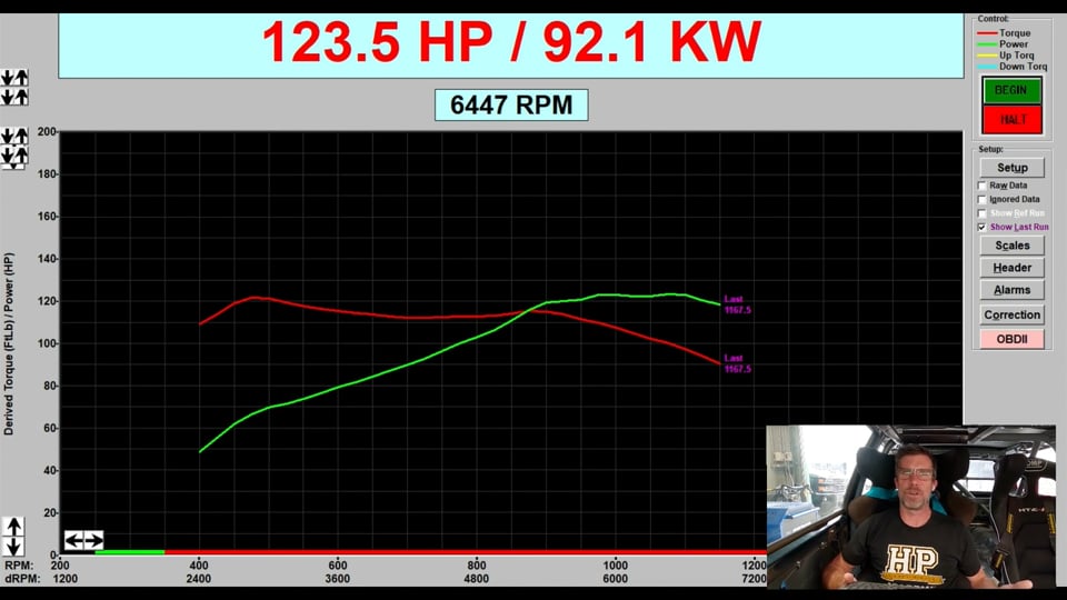
| 27:09 | So, first run complete there, a pretty uninspiring 123 horsepower. |
| 27:14 | Now while I don't have lambda being displayed on the dyno screen, I was watching that and typically a naturally aspirated engine like this, I'm going to tune probably somewhere around about .90, maybe .92 to .88, somewhere in that region. |
| 27:30 | Once we got out above about 6000 RPM, the lambda pretty much fell off a cliff, hit about 0.81, 0.82 which obviously is not going to be helping with horsepower. |
| 27:41 | So what we're going to do is we will save that run. |
| 27:45 | And we'll call that low. |
| 27:51 | Hopefully we'll call that low. |
| 27:53 | So, we're going to be able to overlay our next run straight on top of it. |
| 27:56 | And before we do that, let's jump back into our tuning software. |
| 28:00 | Now what we want to do essentially with this second run is make the VTEC active the whole time. |
| 28:07 | We do need to be a little bit mindful of this though, bringing the VTEC mechanism into play at very low RPM can be problematic, it is oil pressure driven so generally we don't recommend activating that much below about 3000 RPM. |
| 28:20 | If we try and activate it at idle, we're probably going to have it do nothing because we won't actually have enough oil pressure to activate the VTEC anyway, but generally 3000 RPM, give or take, that's a pretty safe place to be. |
| 28:36 | So, we're going to do another ramp run now. |
| 28:38 | So, our VTEC mechanism will be active essentially for most of this run. |
| 28:42 | What we're looking for is the point where the two lines overlay. |
| 28:46 | So, let's head back to the dyno, we'll get our second run done. |
| 29:14 | So, second run complete, 184 horsepower at the wheels. |
| 29:18 | A little bit better, a little bit more like what we're after. |
| 29:21 | Unfortunately, despite me saying that that was going to overlay with the last run, it didn't. |
| 29:26 | So, what we'll do is we'll just switch our engine off for a moment, it's a little bit quieter. |
| 29:32 | And we will save that run and we're going to call this "high", just like we'd expect. |
| 29:39 | So, this will overlay those two runs one on top of the other, which is super helpful when the dyno has managed to rescale that out to 3000 horsepower and unsurprisingly we're not seeing a lot with that scaled out to 3000. |
| 29:57 | This worked perfectly when we were running this before, and now it's not. |
| 30:03 | Which is ideal and I don't know if I'm actually going to be able to see enough of the dyno from here to be able to do this. |
| 30:12 | So let me just see if I can actually unselect all those runs and then we'll bring them back in again and see if that's going to help it. |
| 30:26 | Interestingly I have never had the dyno do this to me. |
| 30:30 | And it's not going to play ball which is awesome. |
| 30:36 | Not something I'm probably going to be able to fix on camera. |
| 30:41 | Essentially what we should have had there is two runs that overlaid on the top of each other which did exactly what they should have done when I tested it before our webinar. |
| 30:51 | And what we're obviously looking for is the point in the RPM range where we see the high cam run overtake and exceed the low camera. |
| 30:59 | It should be a nice clear concise point and then all we need to do is select that point for our VTEC changeover. |
| 31:07 | Now there is a little bit of testing that goes into this. |
| 31:10 | There is a little bit of latency in the system actually functioning, more from a mechanical standpoint. |
| 31:16 | So, generally what I'll do is set my VTEC changeover point at the point identified when those two runs cross, but then I'll do a couple of ramp runs and I'll sort of move that around maybe plus or minus 100 RPM and just see where I actually get that optimised, and where I get the most power under the curve. |
| 31:33 | At that point we should be almost splitting hairs but we've got the ability to do so, so absolutely why not. |
| 31:40 | So, I do apologise that that demonstration hasn't quite gone to plan. |
| 31:44 | Might have to figure that one out after the webinar but the process is pretty straightforward and I think you're probably able to pick up kind of what I was putting down. |
| 31:53 | At the risk of this also failing me, what I might try and do is another test and we'll see if we can do a lower load run and basically demonstrate the fact that the VTEC changeover point is going to want to switch at a higher RPM. |
| 32:11 | So all things being equal, I'm pretty sure based on that VTEC, the VE map, that the VTEC changeover point was at that 3700 RPM range so that's at wide open throttle, 100 kPa. |
| 32:23 | What we'll do now is we'll try and do a couple of ramp runs at about maybe 25% throttle which will be maybe more like about 60, 70 kPa and see how that affects things. |
| 32:34 | So, let's jump back into the laptop software and again we'll start by setting our VTEC out of the way. |
| 32:39 | I will just make sure, oh actually this might work as well. |
| 32:44 | It's really not happy at the moment. |
| 32:46 | Because it won't even show my reference run. |
| 32:49 | Alright we'll get ourselves running, we'll try it and see and if it's not going to work, we will forget about it. |
| 33:04 | Alright, we'll head over to our dyno and we'll get our first run here and I'll try for 25% throttle. |
| 33:37 | First run complete there, obviously it's not making very much power, no big surprises there. |
| 33:43 | We will save that run and if that's not going to show up when I start this run, we will abort it and it's not. |
| 33:55 | So, we're not going to get any further than we already were so I do apologise again for that test. |
| 34:02 | I have no idea why it's decided that now's a good time to play up but it has. |
| 34:07 | But essentially should be able to get the idea there, we can do that at wide open throttle, we can do it at a lower throttle setting and get a sense of what the optimal VTEC changeover point's going to be and then a bit of interpolation is going to pretty much give us an idea of what the curve through the RPM and manifold pressure should look like if we want to use the table that I showed you. |
| 34:29 | For now, with my poor demonstration complete, let's head across to our questions and we'll see what we've got in there and if you've got any further questions, please keep them coming. |
| 34:41 | Chris has asked "In your experience is there usually any benefit in switching the cam lobes independently at different RPMs, intake versus exhaust rather than using one output and switching them both at the same time?". |
| 34:53 | I've done this with the P11 Primera VVL Nissan SR20 cylinder head. |
| 34:59 | The P11 had independent solenoid control for intake and exhaust. |
| 35:04 | And I mean if you do want to get into the nitty gritty on that particular engine, yeah there was a small, but noticeable difference in the switching points for intake and exhaust. |
| 35:14 | Nissan obviously didn't see that as being a deal breaker because in the P12, they went to a single solenoid for both intake and exhaust. |
| 35:23 | We're running a P11 head with P11 cams on our SR20 VVL turbo race engine. |
| 35:30 | And again for simplicity and also partly because it's a North South application installation, to give more room around the firewall, we are running a Mazworx single solenoid modification or upgrade. |
| 35:43 | And yeah, I mean the difference is not significant, obviously not enough for me to be worried about it. |
| 35:50 | Chris has also said, "I see the state for 40 maps, 0-100, traditionally coming from other ECUs it would be 0-1, is this something that's unique to the Maxx?". |
| 35:58 | You're absolutely right there. |
| 36:00 | This isn't something I've actually used a lot in the Maxx, simply because in this car, which we tune, it's an in house race car for our staff here at HPA, we've chosen this simple method because that is what I imagine 95% of tuners are doing. |
| 36:16 | It's 99.9% of the benefit with a lot less work so that's why we've gone down that path. |
| 36:23 | But when testing this and setting it up, unlike the dyno which decided not to play ball, when I tested this and it did work, if you can actually monitor the output of that and it does move from a 0 to a 100. |
| 36:35 | So, pretty easy to just monitor the state and make sure that the numbers you're using in the 40 table actually match with the state that the solenoid is going to, the output is going to. |
| 36:47 | That looks like all of the questions we've got so we will leave it there as usual for our HPA members. |
| 36:54 | If you are watching this at a later point in the webinar archive and you've got questions, please ask those in the forum and I'll be happy to answer them there. |
| 37:03 | Thanks for watching and we'll see you next time. |
Timestamps
0:00 - Introduction
1:07 - Different to continuously variable
1:57 - How does switched cam control work
4:50 - What to account for in your tune
7:31 - VTEC control
9:50 - Hysteresis
11:27 - Output configuration
12:30 - Fuel table break points
16:22 - 4D table use
19:29 - Changeover windowing based on load and RPM
23:29 - Demo
34:40 - Questions


