347 | How to work with 3D scans in CAD
Summary
3D scans are a game changer for accuracy and efficiency in our CAD projects, however the mesh files we get from 3D scanning aren't always straight forward to work with. In this webinar we'll look at how to get setup and work with 3D scan mesh files in Fusion 360 and cover a few tips and tricks to help along the way.
| 00:00 | Hey team, Connor here from HPA and welcome to this week's webinar. |
| 00:03 | So, this week we are going to be having a bit of an introductory look into how to work with 3D scans in CAD software. |
| 00:11 | Specifically this week we're gonna look at some considerations around 3D scans in Fusion 360, or Fusion as it's now known. |
| 00:19 | But a lot of this will translate to whatever software you are using in the CAD space. |
| 00:25 | And I'm just gonna show you a few tricks and tips that I personally like to use when working on motorsport related projects that will hopefully help you with your own projects. |
| 00:37 | So, why would we use 3D scans in the motorsport space, or performance automotive design? And there's a couple of different reasons. |
| 00:46 | Two main ones that I kinda split this into, and one is reverse engineering. |
| 00:51 | So, that's where we potentially have a part that is no longer available or difficult to get, and we can scan it and then recreate that design and have it manufactured ourself. |
| 01:04 | Generally maybe changing it, making some improvements to the design if we can. |
| 01:10 | And that's particularly useful on like classic cars and things like that where maybe some plastic clips are broken in a simple case and we reverse engineer them and maybe 3D print them from there. |
| 01:24 | The other main use, and perhaps more common, I definitely use this approach more, is just using 3D scans as a reference when we're creating new designs. |
| 01:35 | So, it saves us a lot of time with measuring things and it gives us a really good visual reference to allow us to experiment with our design and really get the best thing in the virtual world before then spending the money and the time moving into a real manufactured part, which obviously can be a very expensive process. |
| 01:56 | So, for those who aren't familiar with 3D scanners: essentially what they do is they capture shape and appearance information about whatever we're scanning, be it an object or an environment. |
| 02:08 | And then they use that to create a 3D digital model from. |
| 02:12 | And that 3D digital model is in the form of a mesh file. |
| 02:16 | So, a mesh file, again for those who aren't familiar with this, is basically the 3D model broken down into lots of little faces and elements. |
| 02:29 | I'll actually just bring one up here so we can see, give you a bit of a better picture if we just look at my computer screen. |
| 02:42 | So, this is a 3D scan, it's a mesh file of a valve cover for a Honda K20, we'll get to this more in a moment. |
| 02:50 | But if I zoom in really close here we'll see that this 3D model is made up of all these small little faces here and they're all triangulated in this case because this is an STL file. |
| 03:03 | Again we'll come back to that in just a moment. |
| 03:06 | So, there's all these little faces and they're connected by edges, which are the straight lines we see, and also nodes, which are the points in between them. |
| 03:18 | So, another way to look at this is that each little node or point in between is a data point that's captured from the 3D scanner, and then those points are then joined together with those edges, straight lines, and then that creates the faces, which builds the kind of surface for the model. |
| 03:36 | And a mesh file is kind of a surface representation of it, it's not a solid model. |
| 03:44 | So, the thing with mesh files is they are a little bit more difficult to work with in CAD software than the native files that a CAD software will create, being a 3D solid model. |
| 03:58 | They're more difficult to modify and so on, so basically we need a way of converting them over and then being able to work with them. |
| 04:09 | In some cases. |
| 04:10 | In some cases we don't need to convert them into 3D solid models. |
| 04:14 | But yeah, there's a few tricks around it and just makes working with mesh files a little bit easier. |
| 04:22 | Just a note before we move on from this discussion on mesh files, is there's a few different types of mesh files. |
| 04:29 | As I mentioned before, STL file, which this one here is, where all the little faces are basically triangles. |
| 04:39 | That's generally the most simple and the most common mesh file that's used. |
| 04:44 | And the mesh files are also really commonly used in 3D printing, or it's what 3D printers use. |
| 04:50 | And STL files again is probably the most common type of file that's used in 3D printing as well. |
| 04:57 | But there are a few different types. |
| 05:00 | The main one that springs to mind is an OBJ object file. |
| 05:05 | And that is another type of mesh file where the faces can actually be polygons, so have a different number of sides. |
| 05:15 | And there can also be curved faces as well. |
| 05:18 | But maybe the main difference, well basically what that means is we can have essentially a more accurate 3D model with an OBJ file, although it tends to be a bigger file size. |
| 05:29 | But one of the other key differences is that an OBJ file can also capture appearance data as well as geometry data. |
| 05:39 | So what that means is we can have the color of the object, of the model as well, where this one is an STL, and it just appears gray or whatever color I set it to in Fusion 360. |
| 05:54 | But if it was an OBJ, I could have the real colors of the thing that I've scanned as well there. |
| 06:02 | So that's just a little note. |
| 06:03 | But generally the processes that we're working with today are exactly the same, no matter what type of mesh file you're working with. |
| 06:12 | So, I'll just make a little call at this point that if you have any questions that come up relevant to today's topic throughout this, feel free to ask them in the chat and I'll do my best at the end to get to those. |
| 06:27 | So, I'll just close this and we'll start from scratch just to give you a good idea of how to I get started working with these mesh files in Fusion 360. |
| 06:39 | So, I have, we've done some scans of parts of our Honda K20 engine going in our CRX, and those have been stored as the mesh files that they come out of the scanning software as on my computer. |
| 06:54 | And then this is the part where I'm bringing them into Fusion 360 and I'm going to start working with them. |
| 07:00 | So, generally I've found the best way to get started is by going to this mesh tab here and then using the create, under the create dropdown and going under insert mesh. |
| 07:14 | And then from here I can find it on my computer and I'm going to get this K20 head file here. |
| 07:21 | And I'm just gonna go open. |
| 07:23 | So, this was actually a 3D scan I think done just to focus on the outside of the head, not the actual valve train or bottom with the compression chambers, or anything like that. |
| 07:37 | But still very useful depending on what we're trying to do of course. |
| 07:41 | Under this insert mesh, if we do it this way rather than just opening the file, we can change the unit types here, in our case our 3D scanner is set up to capture in millimetres. |
| 07:53 | So, that's what we're gonna do to make sure the scale is right. |
| 07:56 | And then we can flip the up direction there as well. |
| 07:59 | Just so the top of this kind of aligns with how I have my coordinate system set up. |
| 08:06 | And if it wasn't centred we could also choose to centre and move it to ground to kind of line that up in our workspace. |
| 08:12 | But generally what we're gonna work through soon is basically showing you how to set these up and align them with your workspace so when it comes time to model around them, you get some nice aligned geometry to work with. |
| 08:26 | Because if you just bring them in on an angle, something like that, it can be really hard to work with them and kind of have a logical workflow from there. |
| 08:37 | So, we'll just click OK there. |
| 08:39 | And again you can zoom in and see the mesh here, STL mesh with all these triangular little faces. |
| 08:46 | And if I was to turn it to just shaded, it just appears as kind of a rough model there. |
| 08:53 | Just for reference, this scan was taken with a PL2S scanner so it's quite good at capturing kind of detailed geometry that's relatively small like this, although it's not really aimed for larger objects. |
| 09:08 | But yeah, works well for cylinder heads, engine blocks and things like that. |
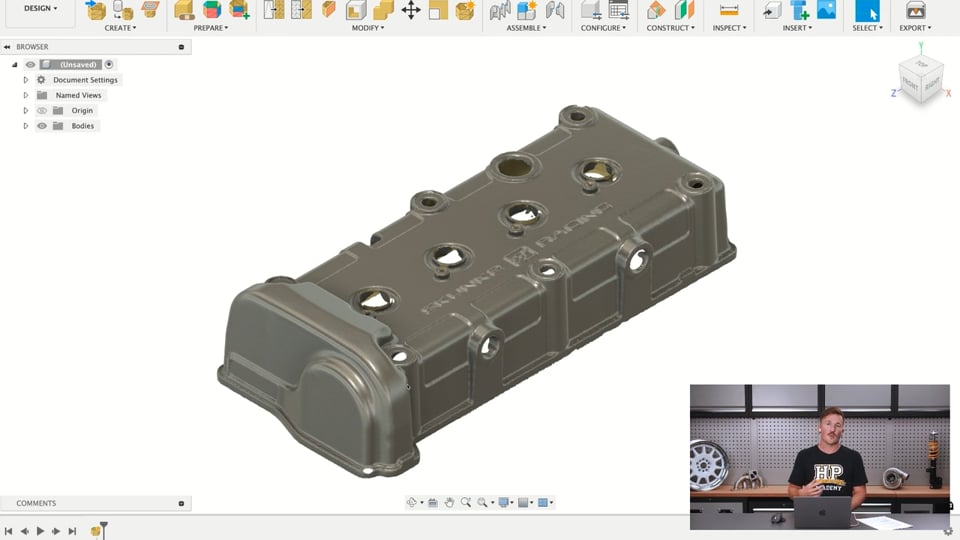
| 09:13 | So, what I have also, I'll open that now in another one, is a 3D scan of the valve cover as well. |
| 09:24 | And this is actually not the original Honda piece, this is the Skunk 2, Skunk Racing, magnesium valve cover and we're just gonna be putting that on here. |
| 09:36 | And we're gonna scan in these when we're designing a whole bunch of things for the refresh of this car in the engine bay so it's good to just have all those parts in the engine bay. |
| 09:47 | Virtually we can design engine mounts and understand the clearance to the bonnet, design the intake and all sorts of stuff like that. |
| 09:56 | So, basically what I'm gonna show you how to do is align this valve cover onto the cylinder head and while we're doing that, that will hopefully kind of show you some other techniques that'll be useful for working with 3D scans for this type of thing. |
| 10:16 | So, if we just jump back to the cylinder head, we'll start with this first. |
| 10:20 | What we wanna do is we wanna make a few datum planes and then those will be used to align the parts together soon. |
| 10:29 | The problem is if we jump down here and go plane through three points and we wanted to click three points say on this top surface where the valve cover would align to, you can see that if I click, even if I have this on showing all the nodes, I can't actually click and select any points. |
| 10:51 | So, we've found a little workaround for this that if you just jump back into the solid toolbar here, and go create form, from inside here I can do that exact thing where I can then select three well divided points on that top surface and then that'll give me a plane on that top surface that I can use to align the valve cover to. |
| 11:17 | The thing is is we need to align the models in three dimensions, otherwise I could just align it to this top surface here but it could be anywhere else. |
| 11:27 | So, to really positively align that in the correct position, we're gonna need three planes just like our origin shows here, three dimensions. |
| 11:36 | The issue, well the thing with a few geometric features or objects like a cylinder head here is they will generally have faces that appear to be at 90 degree angles to each other like those three origin planes. |
| 11:56 | But if we actually come here with our 3D scan and maybe click three points on this where the, I think exhaust manifolds on this side, and we create another plane like this, the issue is if I measure the angle between those planes, you'll see here that it's 89.414 degrees, it's not actually perfectly at 90 degrees, and that basically just comes down to the data of the scan not being perfectly, perfectly accurate. |
| 12:28 | And that means that when I go to align this say with the origin planes in another design file like I'm gonna do soon, we're gonna have a little bit of issues there because the origin planes will be at 90 degrees to each other and these ones won't, so you'll never get it perfectly aligned. |
| 12:46 | So, I'll just come back and I'll delete that second plane we had here. |
| 12:51 | So, we can see on the top here we've captured these holes here which is what the valve cover bolts up to. |
| 13:02 | And I'm gonna use those holes to basically create references on this head and then I'll do the same thing for the valve cover and then we'll be able to bring those together soon and align it, align the two parts together in another design file. |
| 13:19 | So, if I, what I want do is I want create a sketch on that top plane here and then I'm just gonna use the circle tool and I'm gonna jump in here, zoom in and I'm going to start lining up circles with the fixing points for the valve cover. |
| 13:41 | So, I'm just gonna focus on this one here first, make a 10mm diameter circle and just kinda drag that into alignment with that hole. |
| 13:52 | And from there I'm just gonna lock the position of that once I'm happy with it. |
| 13:57 | Now I want to do this, I'll just turn off the 3D sketch preferences on. |
| 14:05 | I want do this for the 4 corner holes for the rest of the cylinder head here. |
| 14:17 | I don't need to do the other ones, just the 4 corner holes work fine. |
| 14:20 | I'll just highlight those holes and I'm gonna click equal so they all have equal diameter. |
| 14:27 | And then I'm just going to kinda roughly get that in position and then use a construction line from the center of this over here. |
| 14:44 | And I'm gonna dimension that construction line to 149mm because I know the actual physical measurement from the head. |
| 14:53 | And then do another one here down from this vertically here. |
| 15:01 | And I can make these two perpendicular to each other, these two construction lines. |
| 15:12 | And same thing, I can dimension this vertical one, I think it was 375.5. |
| 15:22 | And that lines up nicely with that bottom hole as well. |
| 15:28 | So, the thing here is the, although it looks like the cylinder head is aligned perfectly vertically, it might not actually be. |
| 15:37 | So, if I went here and put a horizontal constraint on this, that actually looks pretty good in this case. |
| 15:47 | Yeah, that aligns pretty well, so from that point I can also draw a line over to that one. |
| 15:57 | And if I make those perpendicular, then that squares it all up. |
| 16:05 | And then I'll just make this top line, if I just hide this one, it might be easier to see it easier. |
| 16:10 | Make that top line equal in length to that one. |
| 16:13 | And that fully defines our sketch there. |
| 16:17 | So yeah, when everything goes black, it's fully defined and basically nothing can move by accident in that case. |
| 16:25 | And then this is kind of the little trick that I use from here to basically make those three origin planes at 90 degrees to each other. |
| 16:35 | I'm going to use a 3D sketch. |
| 16:39 | Starting off, I'm just going to come along this line with the line tool again and find that midpoint. |
| 16:46 | So, that's shown by that little triangle there. |
| 16:49 | Select that and leave the active plane here on the bottom one. |
| 16:56 | So, this is kind of the difference with 3D sketches and it's something that we're going to cover in a coming webinar; is being able to change the active plane. |
| 17:04 | And then just going to move that out there and you can see that that's created that point perpendicular there. |
| 17:14 | What I'm going to do is actually just make that point, those two equal and then I will find the midpoint of that line. |
| 17:27 | There's a few different ways you can go about doing this depending on the kind of geometry you've got. |
| 17:34 | Find that midpoint, change the active plane to the vertical one here, then I'm going to draw that up there. |
| 17:42 | And you can see this sketch is no longer fully defined and that just tends to happen when you have curves or circles in it. |
| 17:52 | It's a little bit tricky to get it fully defined but I'm pretty confident in this case that I have all the constraints kind of set up. |
| 18:00 | I'll just make that equal to that. |
| 18:03 | It doesn't matter actually what direction that goes in. |
| 18:07 | But I'm pretty happy in this case that the sketch is still fully defined and nothing is going to accidentally move or anything like that. |
| 18:16 | So, from here, I'll just turn the scan of the head back on and then I can finish the sketch and I can jump back into the plane through three points tool. |
| 18:31 | And then all I want to do, I'll hide the body again. |
| 18:34 | I already have a plane that's flat to that top surface and I want to make some other planes. |
| 18:42 | So, actually, sorry, let me just jump back into that sketch. |
| 18:46 | I've missed one line. |
| 18:49 | I just need a line from that center point here to that point there. |
| 19:02 | And that'll be enough now. |
| 19:06 | So, then I'm going to use the plane through three points tool and I'm going to make the two other planes that I need. |
| 19:12 | So, I'll need a kind of front plane here through these three points and I'll also need another plane here and I can use these three points here. |
| 19:25 | Then if we show that one again, show the body again. |
| 19:30 | If I measure the angle between these planes, you can see that it's perfectly 90 degrees now between all three of them. |
| 19:40 | So, they're all 90 degrees. |
| 19:42 | And from there, I can just close that and I can finish the form tool there. |
| 19:49 | And then basically save this and I like to save this as something like, so this is a K20 head scan and that'll just save into our data, what's it called, data panel here and I can use that in a moment. |
| 20:07 | So, this is how I like to set up the 3D scans is bring them into their own design file, set up the planes and then leave that all in its own design file, save it and then soon we're going to bring that into another design file as a component, and that way we can align things and keep the planes all, I guess, in the position that they need to be in. |
| 20:29 | And I'll show you also the issue is if we don't do that, if we take the other approach as well. |
| 20:35 | So, from here, we're basically just going to do the same thing. |
| 20:40 | In this case, what I want to do is again jump into that create form tool to allow us to first create a plane through three points. |
| 20:53 | The bottom of this is kind of a sharp edge and it's not going to be really good for creating a plane on, although that's where I want it to be. |
| 21:02 | So, I'm just going to take another step here. |
| 21:04 | I know the top of the valve cover here is a nice flat surface that's parallel with the bottom surface. |
| 21:11 | So, I'm just going to create a plane through three points on that top surface. |
| 21:16 | Then I'm going to do an offset plane from that down to level of the bottom which happens to be where our origin is. |
| 21:23 | I just don't want to use that bottom origin plane because I'm not 100% sure it's aligned with the scan properly. |
| 21:29 | And there we go. |
| 21:30 | And then I'll just go into here, hide that top one. |
| 21:33 | So this plane here is going to be used to align with the top surface of the cylinder head that we also had a plane on just before. |
| 21:44 | And now I just need to make the same planes centered between those mounting holes as well. |
| 21:50 | And we'll use those to align the two parts with each other in just a moment. |
| 21:56 | So, if I just start here, again, I'm going to sketch on this and these are the mounting holes here. |
| 22:06 | So, follow basically the same process here. |
| 22:12 | Might make that a little bit bigger so it's just easier to align. |
| 22:18 | Put that in the middle there and then lock the position of that. |
| 22:25 | And then I'm going to do the same thing and put a hole, sorry, a circle in the middle of each of those four points. |
| 22:42 | Then you can highlight them again and go equal constraints so they've all got equal diameter. |
| 22:50 | Then I'm going to use basically the same process of aligning those. |
| 22:57 | See if I can put horizontal on that. |
| 23:01 | Looks good. |
| 23:03 | And I think this was 149 spacing. |
| 23:09 | And this vertical one down here. |
| 23:18 | Make that perpendicular. |
| 23:21 | That vertical one was 375.5 I think. |
| 23:30 | Little bit off but it'll be plenty good enough for this. |
| 23:39 | Same thing here. |
| 23:41 | Just turn that body off. |
| 23:44 | Make these lines equal. |
| 23:49 | That perpendicular and that's fully locked in that scan. |
| 23:53 | And then I'm just going to follow basically the same process as before to make this 3D sketch in just a moment and get those points so I can use the plane through three point tool to make three equal, three 90 degree planes. |
| 24:14 | 3D sketch preference on. |
| 24:17 | Select the line tool. |
| 24:19 | Select that center point. |
| 24:20 | Change the active plane to the vertical plane and do that. |
| 24:24 | And you'll see again it just clicked off being fully defined because of those curves but not too worried about it. |
| 24:33 | Oh, almost forgot again. |
| 24:37 | From here to center point there and finish sketch. |
| 24:44 | And then again I can use the plane through three points tool. |
| 24:49 | Get that front plane and that other plane there. |
| 25:00 | So, we're in the same position as what we had with the cylinder head. |
| 25:04 | Finish the form. |
| 25:07 | Save that as skunk to valve cover scan. |
| 25:16 | Save. |
| 25:17 | So, then what I'm going to do is create a new design and this is kind of going to be the master assembly design and before I insert anything into this new design I also need to save it. |
| 25:27 | So I'm going to call this K20 assembly. |
| 25:35 | Save. |
| 25:37 | I can jump into the data panel here, and I want to align the head scan into that. |
| 25:46 | So, insert into current design and that will drop that in there. |
| 25:55 | And we can see our planes there and what I want to do, I'll just drag this out of the way a bit, is align that with the origin planes there. |
| 26:05 | So here we modify, go align. |
| 26:09 | I'm going to start with this one here and I know that this part here of the head is actually on the back of the engine so I'm just going to flip that around. |
| 26:17 | Then I can align those ones. |
| 26:20 | Flip that so it's back out the right way. |
| 26:23 | And then align that one. |
| 26:27 | So, those three planes are aligned with the origin point. |
| 26:30 | Now the origin point is directly in the centre of all those mounting holes there. |
| 26:35 | And yeah, pretty happy with that. |
| 26:38 | So, the key point here is to remember to right click that component and hit ground and capture the position. |
| 26:45 | So, that's just a move that we made. |
| 26:48 | So, we're sure that that isn't going to move anywhere when we do the next step, or when we're working on maybe designing something new for this, we don't want things to just go floating around. |
| 27:00 | We might not notice if it moves a couple of mils and then our whole design can be off when we actually come to fit it in the future. |
| 27:09 | So, same thing here, I'm going to go back to the data panel, insert the valve cover into the design and that already looks pretty aligned but it's not quite. |
| 27:23 | So, just drag it out so we can see what we're doing. |
| 27:26 | Same thing here and I'm going to align these planes. |
| 27:37 | And where's the top one? This one, that one and that one. |
| 27:55 | Now we can be pretty sure it's not got the front kind of timing cover area on it but that that is all aligned if I turn off the construction planes. |
| 28:09 | That's nicely aligned there on the top. |
| 28:12 | We'll just take, change that and I'll turn the sketches off as well just to tidy things up. |
| 28:23 | And the same thing here, there's two options. |
| 28:25 | We can either choose to ground that component as well or we could choose to create a rigid group between the two components so they're basically locked together and can't move. |
| 28:39 | So the reason that I do that, just saved it quickly there, is if we don't do it like that and say we just went into this one here and did the same thing and inserted a mesh of the valve cover into this and flip the up direction, just move this over here; and let's say I did the same thing and I created the planes on this, so let's jump in and do that. |
| 29:17 | Plane tangent to the face, and let's say I started and for some reason sorry, wrong one, plane through three points; and I started and I wanted to for some reason align this plane to this one here. |
| 29:32 | The issue you can have here, and it doesn't always happen, is that when you hit align between bodies say and you choose the two planes it's not even going to let me do it here. |
| 29:51 | It's not going to let me do it. |
| 29:54 | So, basically what happens is the plane will just move off the part and it'll just move away from it and it won't actually be locked to the part and that can be pretty frustrating. |
| 30:04 | So it's a much better thing to have them set up as their own design files and then move through and set them up like this in another assembly and then we can work from there. |
| 30:18 | And as you can imagine we could work from here, create a plane say on this intake here and then find the edges of that and start making something like the flange for an intake manifold or something like that. |
| 30:35 | So I'm just going to say again, you can also use the same method for aligning parts, let's say you have a model of an intake manifold you could bring it in and kind of follow a same method there and align those parts there. |
| 30:52 | Before I move on to the last point I'm just going to ask again if you have any questions related to what we're working on today then go ahead and ask them in the chat and I'll do my best to answer them at the end, anything CAD related, 3D scan related. |
| 31:09 | So, just one last trick I'm going to show which is really, really helpful when working with meshes or 3D scans and we'll just jump back perhaps, no we'll do it in this file here. |
| 31:23 | So, if I just create another plane let's say on this surface say the valve cover, sorry the intake surface here, create another plane and then I'm just going to offset that back in by half a mil or so, see how that works, we might need to adjust that in a moment. |
| 31:59 | Finish form, from here if we go to the mesh toolbar here this create mesh section sketch is a super powerful tool if you're working with reverse engineering parts or just using them as a reference as well. |
| 32:16 | So, basically if we click this what it does is if we select the body we have to jump in here, find the body, we might need to do this in the other file sorry jump back, do it in the actual scan of the head instead. |
| 32:38 | Turn those off, do the same thing, jump back in here, edit the form, create a plane through three points on this and then we'll just offset that back into the head 0.5 mil turn off that one here. |
| 33:02 | Ok, now we should be able to go to mesh, create section sketch through this mesh body and use that as the section plane and you can see this kind of orange profile it has come out of here it's actually created a sketch of this section as it cuts through the part and that's really helpful for finding the profile of 3D scanned parts. |
| 33:26 | So, if I just click ok there, can turn that plane off and we can go back here to create these two, the sketch here and then the mesh section feature in the timeline as well, and I can jump back into the sketch and edit the sketch, and then it just kind of comes to the other key point of this tool: if we go to the create drop down here and go fit curves to mesh section then we can jump into this and depending on the mesh section we can fit curves to this. |
| 34:04 | So, for example you can fit a spline here or a closed spline let's say to this here and yeah I think that worked and then change the tolerance there too that kind of like can smooth it out it's not really liking that one for whatever reason. |
| 34:31 | Oh yeah, it has so you can see here now I have that profile inside there where I don't have it for those and I could use that once I have that profile to create a 3D body from that I'll just jump back in and a really handy one is the circle one here, and we can click, you know it's picked up on this kind of hole so this is a really good way of also finding the center of holes in a scan. |
| 35:02 | Click circle, select that and it will fit a circle there and it will give you that center point for that hole and we can just hit Ok, and now we have that center point for the hole. |
| 35:17 | We could also jump in and create a axis here. |
| 35:31 | No, doesn't want to do it, I'm not sure on that tool actually, but you can create an axis through two points if we drop that back slightly further. |
| 35:41 | I'm pretty sure you can do one perpendicular at a point I thought you could do that, face sorry. |
| 35:47 | So, there, anyway you get the gist, but now we have this profile and we can use that to create whatever model we want from that. |
| 36:05 | So, in this case not particularly useful what I've just done, but as you can imagine if you have a scan of a profile you can go through and basically use this to create a parametric model of all the parts there and if I went back into this here, and I fit curves to the mesh section and basically did that to all of the outside of this flange profile here then I could create the flange profile and then I'd be able to go out of here and use the extrude function to be able to extrude that flange say 10mm thick or something and start modeling an intake manifold from there. |
| 36:48 | So, I will just leave it at that for this process, but just to summarize the kind of key points here: we went through the process of from the mesh toolbar, inserting the mesh then we went into the form tool and we created the plane through 3 points on a nice flat surface we then used a sketch and a 3D sketch inside that to create kind of a reference structure and then used the plane through 3 points tool again to create 3 planes at 90 degrees to each other. |
| 37:23 | We then saved that as its own design file and bring that into an assembly file, and then we can use that to align that with the origin of that assembly file, and also align parts and other scans together through that method; being sure to ground them as well so they don't move when we're aligning things or just doing any other work. |
| 37:47 | And then those 2 key points is creating that mesh section sketch and then after we have the mesh section sketch we can then go under here and fit curves to the mesh section so we can use that to create profiles and then move from there onto 3D solid modeling. |
| 38:05 | So, that basically wraps up that and I'll just jump over to my notes and see if we have any questions for today's topic. |
| 38:25 | "Joel what would be your minimum requirement for resolution for scanning non-internal engine parts like say plastic parts like timing covers etc.?". |
| 38:36 | So, resolution just for reference is kind of on par with accuracy really. |
| 38:45 | If you're using a smartphone the resolution might be in the range of a couple of millimeters or if you're using a professional scanner, say anywhere between the range of a few thousand dollars to maybe fifty thousand dollars, you could be in the range of 0.1, 0.2 millimeters for resolution and accuracy. |
| 39:10 | I would say for non-internal engine parts especially things like plastic covers you really don't need it to be that accurate. |
| 39:18 | And if the resolution isn't that good, if you're working from a smartphone or something like that, you can just back it up with measurements that you take from the parts just to make sure that say you do the scan, you design something and you just want to be sure that the measurements that you think like the distance between holes are correct, and your resolution isn't very good, you can just take a measurement of it and check that it's correct before you go and get it made 3D printed or machined or whatever you're going to do. |
| 39:47 | So, for something yeah non-internal engine parts I'd say a couple of millimeters is going to be fine, but a proper scanner that's kind of down to fractions of a millimeter is going to be perfectly suitable anything like above that which is just really expensive scanners for specific like measurement studies and stuff like that is just really not necessary at all. |
| 40:13 | The scans that we've used from iPhones in the past like we created the billet valve cover for our SR20 was just done off a 3D scan from an iPhone with not great resolution, not even a LiDAR capable iPhone. |
| 40:30 | So yeah, doesn't need to be too critical unless you're doing things that are really really need that accuracy. |
| 40:40 | So, "just to have a little note here, scanned a Mach 5 gearbox and got 60 million points want to know what settings we suggest and why? So please cover...", yeah Ok. |
| 41:04 | So, you can reduce the amount of points if you have 60 million points it's going to be a massive mesh file, if I just jump back into Fusion 360 here under the mesh toolbar; we've got all these different tools for working with meshes and that might even be difficult to just open in Fusion 360 depending on your computer. |
| 41:27 | If you do manage to open it you can use this reduce function here and basically what that'll do is just reduce the number of faces or groups in that. |
| 41:39 | So, in this case if I put 25% that would lower that So, you'd get 25% of 60 million, 25 million I guess faces. |
| 41:48 | so you'd want to reduce that massively. |
| 41:50 | You don't need probably anywhere near what you think. |
| 41:54 | I'm not sure, it depends on the actual settings that you're working with with your scanner will depend on the software that you're using and your scanner, but again if you're working on a small object that you want to be detailed then using a high resolution with a lot of a highly refined mesh will be useful. |
| 42:21 | If you are like wanting to scan the engine bay it doesn't need to be that high refinement. |
| 42:29 | So, at that point I could probably lower it right back down to a much lower setting it just depends on what you're working on. |
| 42:37 | Especially if it's a big area you probably don't want it to be really refined anyway because it'll just be a massive file. |
| 42:43 | I think you said your Mark 5 Golf gearbox. |
| 42:47 | So, in that case I'd probably yeah it doesn't need to be that well refined, but yeah trial and error for sure. |
| 42:59 | That depends on what you're going to use the scan for in the end. |
| 43:04 | "Joel, will all this translate over to being usable in the hobbyist version of Fusion 360?" I think it probably would from what I understand all of these files, all of these features are available in the free version, the only thing I question and I'm not able to check right now is to create mesh section sketch and use of the form tool, but from what I understand it's all is definitely useful in the free version of Fusion 360. |
| 43:38 | And obviously it's the same program. |
| 43:41 | And then if you were using another program like Solidworks or something like that the same idea would apply if you're trying to align things to each other you'd probably use what's called mates in Solidworks, but same thing you'd want to create planes or features using holes and things like that to align things and you just always want to align things and to be straight in those three dimensions. |
| 44:11 | It just makes it so much easier when you come to design parts in the future, when if something's just skewed on a strange angle it's just frustrating to say the least. |
| 44:21 | If it's straight nice and aligned you can use your constraints inside sketching like horizontal and vertical and things like that and it just comes together so much nicer. |
| 44:32 | And if you ever need to make changes to it from there as well it's just like a completely different thing. |
| 44:43 | Oscar Boutinna: Sorry, I probably butchered that. |
| 44:49 | "Please cover 3D scanning techniques, point cloud, fusion and mesh settings to get the optimal data." Yeah, I think we'll probably come back to that in a coming webinar inside the actual scanning software itself. |
| 45:05 | We did cover kind of an introduction to 3D scanning using our Peel system, but we haven't yet got into the actual setup for, I guess, optimal data but again it depends on what your use for it is if you need that or not. |
| 45:25 | Richard Jones: "I scanned the frame of my formula car steel tubes with various 3D bends that I want to modify, but I'm baffled on where to start. |
| 45:36 | I have the mesh in fusion but I need to do 3D sketches from that." Yeah, I have tried this before. |
| 45:45 | So, there is software that's generally really expensive that will automatically convert 3D scan features into solid models for you that then you can modify as well. |
| 45:57 | Otherwise this is probably more along the lines of what you're going to need to do, creating those mesh section sketches and through different points and then fitting splines or 3D sketches to those, finding the center lines of the tube structure is probably what I'd assume, and then using probably the pipe tool in Fusion 360 is a really good way to build weldments or tubular structures like that, that's what we used for our CRX subframe. |
| 46:33 | So, I hope potentially what we've used in this webinar should be a good place to start I think on doing that, using those planes to create mesh sections and fitting curves to that and then kind of going from there, because you're going to want to basically recreate the mesh structure in a series of proper solid model tubes so you can modify it from there. |
| 47:01 | You can't really just use the mesh file and modify it definitely not to create what you're trying to do with that. |
| 47:09 | So yeah, again I hope this kind of helped point you in the right direction. |
| 47:15 | But if you are part of our forum, CAD forum, then asking questions on there and being able to share files and things like that, we tend to jump in and try to help out as much as we can there and it helps a little bit having a bit more of a clearer picture of what you're exactly doing and being able to recommend places to start. |
| 47:33 | If you are on our forum I recommend setting up a post there and going from there; so yeah hopefully I'll see that on there. |
| 47:40 | Just before I finish up I just want to note that we have done introduction webinars to Onshape, Solidworks, Fusion and FreeCAD as well in previous webinars, and we are starting to do more topics through these webinars like this as well as some things of how to model certain automotive or motorsport parts giving you some insight into I guess worked examples on real parts that we use on our cars or other projects. |
| 48:11 | But if there are any specific topics that you want to cover related to CAD or different CAD programs, please let us know in the comments or in the chat and we'll do our best to get to those in the future. |
| 48:24 | But we'll finish at that and we'll see you next week with another webinar, so thanks for watching. |
0:00 - Introduction
0:37 - Why use 3D scan in motorsport?
1:56 - 3D scanners & mesh files
4:22 - Types of mesh files
6:39 - Bring files into Fusion
9:56 - Start: align valve cover onto cylinder head
13:19 - Create references for cylinder head
16:39 - Using a 3D sketch
20:07 - Summary of setting up 3d scans
21:11 - Redefining origin plane for valve cover
21:56 - Finalise all planes for valve cover
24:04 - Applying 3D sketch to valve cover planes
26:09 - Aligning in new design file
29:27 - Aligning issues
31:23 - Easily find profile of 3D scanned parts
33:26 - Fit curves to mesh section
36:05 - Parametric model for parts
36:51 - Summary
38:25 - Q&A


