349 | Learn 3D sketching in Fusion 360
Summary
3D sketches are a great way of quickly creating weldments, like roll cages, subframes or even tube chassis in CAD. As you'd image though they are a little bit more complicated to create compared to 2D sketches. In this webinar we'll cover the fundamentals of creating 3D sketches in Fusion 360 and the various areas we can use them in motorsport design.
| 00:00 | Hey team, Connor here from HPA and welcome to this week's webinar. |
| 00:03 | So this week we're gonna be having a bit of an introductory look into using 3D sketches inside CAD software. |
| 00:11 | Specifically this week we're gonna be working in Autodesk Fusion but as with all of the CAD topics that we cover, if you understand these skills and techniques in one software it's absolutely transferable and applicable to any other software you might be working in. |
| 00:27 | So, we're gonna start off with a bit of a discussion about how we would use 3D sketches in motorsport design, and for our project cars for example. |
| 00:38 | And then we're gonna talk about how 3D sketches differ from 2D sketches in CAD, and then also give a bit of a demo of modelling a few things using 3D sketches, because that kind of gives you the best insight into seeing it used in a practical situation. |
| 00:56 | So, let's first talk about the use of 3D sketches in motorsport design or designing parts for our project cars. |
| 01:04 | In CAD terms, we'll start off with this, we use 3D sketches most often for sweeping a profile along a trajectory. |
| 01:17 | So, if you think about sweeping a cross section along a path and where that trajectory needs to be in three dimensions rather than two, so if it needs to move off a single plane into 3D. |
| 01:32 | So, we can do sweeps with the sweep tool obviously or we can also do it with the pipe tool. |
| 01:39 | The pipe tool, we're gonna cover all this very soon, is just a tool to basically make sweeps a little bit easier where the cross section is kind of predefined as a circular cross section or a rectangle for example. |
| 01:55 | So, in motorsport where this is really useful to us, kind of the area that I've used it the most, is in creating weldments. |
| 02:05 | So, basically that is a structure of parts that are welded together, roll cages, sub frames and even things like tube chassis as well. |
| 02:14 | That's a really good place to use a 3D sketch to kind of map out that structure first and then use something like the pipe tool to then bring that to life. |
| 02:23 | Again we'll be covering that in a moment. |
| 02:26 | Also, you could probably imagine if we can use it for tube structures like that, then for the plumbing, motorsport plumbing, it's also a really good tool for planning that out as well. |
| 02:39 | And if we wanna get more complex with it, some surfacing, making aero parts as well. |
| 02:47 | It's a really powerful tool for that and that's kind of yeah, at the more complex end of things. |
| 02:53 | But again we'll have a little look into how to do that today. |
| 02:57 | This is more of a kind of introductory fundamental look at 3D sketches though. |
| 03:02 | I'll just make a call now for questions that, if there is any questions that you come up with relevant to today's discussion or any CAD topics, feel free to drop those in the chat and I will do my best to answer those at the end of the webinar. |
| 03:19 | So, let's get started in the kind of practical work. |
| 03:25 | First, we just wanna compare 2D sketches to 3D sketches and kind of understand where the difference is. |
| 03:31 | Obviously it sounds pretty obvious, one's in two dimensions, one's in three dimensions. |
| 03:35 | There's a little bit more to that especially inside Fusion. |
| 03:39 | So, any sketches in Fusion can be 3D or they all are 3D by nature. |
| 03:46 | It's just that a 2D sketch that we're working on will not have any features in 3D. |
| 03:51 | But it's very easy to just change that sketch to a 3D sketch. |
| 03:56 | Nothing specific about the feature being a sketch feature actually changes. |
| 04:03 | The key difference is a 2D sketch obviously lies on a single plane and a 3D sketch we have the ability to bring that off that active plane and basically change the active plane as we go. |
| 04:16 | Again, this is gonna make more sense as we start doing the work. |
| 04:22 | So yeah, we'll just get into it here. |
| 04:24 | I'll just hide these canvases for now. |
| 04:27 | We'll get a bit of an understanding about how all this works and then come back to that in a moment. |
| 04:35 | So, if we start a normal create sketch and then we're prompted to select the plane. |
| 04:41 | This is the general way that we'd start a 3D sketch. |
| 04:44 | So, if we just sketch on that top plane there and I'll just pull that 3D sketch off there for a moment. |
| 04:51 | So, a 2D sketch, let's say for example we are working with a rectangle here and that's just our 2D sketch lying on that plane there. |
| 05:04 | And we can very easily change this into a 3D sketch. |
| 05:08 | So, if this for example has some dimensions on it, yeah let's say 3000, so that's 3 meters by 3000. |
| 05:24 | Then that's fully defined and we won't be able to do anything with this. |
| 05:27 | So, if I use the move tool which is under modify move here or quick key M, and I try to move a point, I can't move it because it's fully defined. |
| 05:40 | So, if I take off this horizontal constraint here and here, it still probably won't let me move it because of these dimensions here. |
| 05:53 | We'll just give that a shot. |
| 05:56 | Click here, drag it up and it won't. |
| 05:59 | If these dimensions were done just to the line width length, it wouldn't be a problem but we'll just delete those and here if we select move, we can click that point and we'll be able to drag that up off that plane. |
| 06:13 | So, you can see already that has become a 3D sketch. |
| 06:17 | You can see that these lines here are laying flat to that plane because they have these horizontal constraints on them and then this point here we were able to drag that up and move that into 3D space. |
| 06:29 | So, that's one way to do it. |
| 06:31 | The other way is if we click this 3D sketch preference down here in our sketch palette and then start to draw with a line for example, we can click here and you can see the key difference here is that we get this kind of coordinate system come up and this allows us to change the active plane that we're working on. |
| 06:57 | So, the blue one here which is the bottom plane, top plane is selected so if we started sketching the line out from here, then it would stay on that plane, but we can basically just click to select this other plane and then we can move up, it's kind of hard to visualize it, but up into this space here on that plane, same thing with this one here. |
| 07:24 | And you can see that the line will snap into those points in line with those axes to be in that vertical or horizontal constraint and we also have the ability here to rotate that if we wanted as well, if we wanted to work on the plane on this angle for example. |
| 07:45 | And with all of this we can also use all of the same constraints, it's just now we're working in another dimension, it takes a little bit more thought of how that's all going to work, but it's very easy to just make these two lines equal length for example and we can do that with any of them. |
| 08:06 | That's an example but yeah, all of these same constraints can be applied. |
| 08:13 | So, we'll just finish that sketch and delete that. |
| 08:17 | So, that's kind of the basics of getting started with it, but we will jump in and show something a little bit more useful. |
| 08:26 | So, what I showed there was basically the two kind of key ways that you'd use 3D sketches. |
| 08:34 | So, one is with the move tool and then the other one being, yeah, the move tool to drag and move the part around into 3D space, and the other one being with that 3D sketch preference selected in the sketch palette and then changing the active plane and working from there. |
| 08:53 | So, we'll start with the move tool and kind of show an example of how we can use that to create something in 3D. |
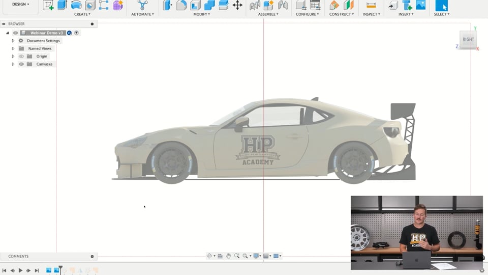
| 09:02 | So, I'll just turn these on here and I'll turn the origin off and this is just two canvases which are 2D images of the HPA SR86 endurance race car just laid out on our front and our right planes there and just kind of aligned with each other. |
| 09:21 | So, if we look at the front, that's straight front on to the car and if we look at the side, that's straight to the side there and for whatever reason, this is just an example today, let's say that we're going to want to copy the shape of the windscreen in 3D. |
| 09:41 | So we'll start off and we'll just sketch on the front plane and what we're going to do is basically just trace half of the outside profile of the windscreen here, and then we'll go from there. |
| 09:58 | So, we'll turn off the 3D sketch selection for now and we'll just create a line straight up from the bottom of the windscreen to the top here and what I'm going to do is just also remove that vertical constraint off there, because we're going to do something a little bit different with that line in just a moment. |
| 10:22 | So, from here I'm going to grab the spline tool and choose the control point spline and then basically copy the outside shape of the windscreen and we're obviously not doing this really really precisely because it doesn't need to be. |
| 10:50 | So, I've come along the top here and down the side and I'll just do the same thing on the bottom edge of the windscreen here. |
| 11:01 | So, I'll just come straight out there. |
| 11:08 | So, we kind of have that profile of half the windscreen there and we'll use the mirror tool in just a moment to create both sides basically. |
| 11:21 | Something else I'm just going to do here kind of jumping ahead is just make a construction line come straight out horizontal here and it's already done it for me. |
| 11:31 | I just turn those canvases off where this line here is tangent to that construction line. |
| 11:40 | I just want to make sure that's horizontal and that'll just make the outside shape of the windscreen basically this bottom edge blends nicely into the other side. |
| 11:50 | I can probably do that with the top one as well. |
| 11:55 | Same thing it's just gone tangent there but I'll just make that horizontal like that. |
| 12:01 | So, that's all good. |
| 12:03 | That's the kind of 2D profile of the windscreen as it's projected to us if we look straight at the front of the vehicle. |
| 12:10 | But obviously that doesn't match if we look at the side of the windscreen the kind of convex nature of it I guess from the side here. |
| 12:19 | So we're going to use that move function to basically drag these parts or this sketch into three dimensions. |
| 12:29 | So, move copy tool we can select oh sorry if we come back and edit the sketch we can view it from the right hand side and we can select the move copy tool here or we can just hit M. And I'm just going to make sure that I'm selecting the right point here. |
| 12:53 | View from the right plane and I just want to drag this out to be basically in line with that top edge of the windscreen. |
| 13:04 | Hit OK. |
| 13:06 | And this is just going to be a bit of rinse and repeat here of working around the windscreen and doing the same thing. |
| 13:15 | Just dragging these points out into space in line with the part in three dimensions. |
| 13:25 | So, that's the two edges there. |
| 13:28 | That one there is going to come with it. |
| 13:33 | Might just have to actually delete that horizontal constraint. |
| 13:42 | Because that's going to mess things up for this front line. |
| 13:47 | So, again move tool on this point. |
| 14:06 | Do this top corner here. |
| 14:09 | You can see as we drag it out to line up with that and then the blue line because this is a control point spline the blue lines the actual spline will basically conform to the outside of the windscreen as we get a little bit further around and get more of these points out on the actual windscreen. |
| 14:45 | Just a matter of working around to get all those points lying on the outside of the windscreen. |
| 15:04 | For some reason the bottom one just jumped back so I have to move that back out. |
| 15:12 | I think what we got going on here is this constraint causing some issues. |
| 15:31 | All right sorry might have to just fix that up quickly. |
| 15:48 | What I'm going to do is just delete that. |
| 16:00 | Jump over to here. |
| 16:02 | So, had to skip ahead a minute there it was playing up but basically what we've got is all of those points just dragged over to be in the same shape as the windscreen here. |
| 16:14 | So, once we have that done then it's just a matter of selecting if we want to bring this into 3D selecting the patch tool here and we can choose that outer shape of that and we can see that that is kind of created half of the windscreen there. |
| 16:36 | And then from there we can also mirror this through the right plane here and join those two together. |
| 16:51 | But the issue we have is this kind of edge that we get in the middle here. |
| 16:56 | So, there's kind of a bit of a trick to that goes along with the 3D sketching that we can use to get rid of that. |
| 17:04 | So, if we create another sketch on any plane it doesn't actually matter. |
| 17:11 | You'll see if we project with our normal project tool and we project that it'll project that onto the plane and we get another 2D sketch again. |
| 17:20 | But there's a way that we can also project edges that are in 3D so I clicked the mirror tool there. |
| 17:27 | So, if we jump down to project here and we go include 3D geometry then we can just include the outer edges of this like that. |
| 17:44 | And if I hide that body we can see that's just basically created the full windscreen there and then we can go back and select patch like that and go from there. |
| 17:56 | And if we wanted we could also create another sketch for example here. |
| 18:01 | Actually, I'm going to jump back. |
| 18:08 | If we did that before this here. |
| 18:11 | Created another sketch here that had that and we did the intersect tool. |
| 18:21 | Get the two points where we intersect that plane on that sketch and then we could create an arc between those and that would kind of control how convex the windscreen is. |
| 18:40 | And if we jump back over to our patch we could use that feature here as interior rails and points and select that and you can see that that's kind of dragged that out where without it the windscreen was a lot flatter. |
| 18:53 | Obviously I haven't matched that to the actual canvas there. |
| 18:58 | But yeah you can see how you'd then get into more surfacing type things to basically control the shape of that windscreen. |
| 19:08 | So, that's one way to use the 3D sketch tool to using that move function to drag things into 3D. |
| 19:20 | But we'll just look at a slightly different option here, and we'll basically show the other option which I kind of more typically use for this stuff and that's what I would refer to as creating a construction frame. |
| 19:37 | So, that's using construction lines to build the frame in three dimensions and then basically connect those points up and that's using the active planes. |
| 19:49 | But that'll make a bit more sense when we get into that just now. |
| 19:53 | So, if we start another sketch we'll start with a 2D sketch on this plane here and let's say we wanted to design the roll cage for the car. |
| 20:01 | Obviously we wouldn't be doing it with a canvas of the outside of the car. |
| 20:04 | We'd probably, if we're gonna do it in CAD, if we weren't just working off measurements it would be best to have a 3D scan of the interior of the car. |
| 20:13 | But this will still give you a good insight into how you'd use this tool for making a weldment like this. |
| 20:20 | So, we'll just start with construction line and we're just working in two dimensions for now and we'll just sketch kind of along that roof line here. |
| 20:37 | We'll come down to about where the inside of the door is and then come down to I'd assume the floors maybe somewhere around here like that. |
| 20:48 | That should be enough there and we'll put some constraints on these just to lock things in and put some dimensions on them as well. |
| 21:02 | So 600, that's a bit high, 550 and we're just going to use these construction lines for that kind of construction process and then bring that into 3D in a moment to build the full kind of structure. |
| 21:37 | So, basically what we're starting with is sketching out the main hoop and if I come along, take the line type off construction and I'm going to start sketching the parts that are actually going to be the subframe. |
| 21:58 | A little bit of a different way of doing it here I guess, just doing those and then I can use the arc tool to draw in between because obviously can't have sharp corners in our tubes unless they're cut and welded together which would be really weak. |
| 22:22 | Just make sure that we're going from the arc to the line that's not the construction line and then depending on what tooling you're using will depend on what radius centre line you can have for these arcs. |
| 22:39 | In our case we have 6 inch centre line radius dies for bending our tubes so we'll put that there and then just use that equal constraint between those two and for now we'll just finish that sketch and then we'll jump into the pipe tool here and we can create the pipe, and that's obviously way too big but we'll just change this to the right size for roll cage tubing which is 44.5 or thereabouts and that'll be hollow with 2.6 mm diameter and modelling everything kind of accurately as an accurate representation here will give us the ability if we did the whole roll cage design obviously to understand the weight as well once we're done. |
| 23:29 | So, if I just hide those canvases we can just see that's half the main hoop there and we can mirror that through the mirror plane there, have that join and that's the full main hoop. |
| 23:44 | Obviously a real main hoop is a bit more intricate compared to this or a bit more, has probably some other features, but this is again just showing you how you'd use this to design, use a 3D sketch to design something like this. |
| 24:01 | So, if I just jump back into the sketch here, now we're going to do the parts that bring this sketch into 3D. |
| 24:08 | So previously this would just be obviously a 2D sketch, I'm going to select the 3D sketch icon here and the line tool and I'm going to build the rest of this frame to kind of plot out those points in 3D space for our roll cage. |
| 24:25 | So, I'll turn the canvases back on as well there and just start by selecting this bottom line here, look from the right, I'm going to choose that as the active plane, and I'm going to come out to about here and then I'll leave that point just floating like that, just to define that, make that 760, and one of the points I want to make here is that often when we're working with 3D sketches and we have curves in them, it's quite easy to basically have these lines blue here which means they're not fully defined. |
| 25:19 | I wouldn't worry about it too much, I generally really like to have my sketches fully defined so all the lines are black and they can't change without me knowing and go floating around. |
| 25:30 | In the case of a 3D sketch, when you have these arcs, it gets a little bit kind of more complicated because I guess the arc could move through three dimensions a little bit differently to a straight line, but in this case, these are all tangent to lines that were fully defined, yeah, it's just not something that I'd really stress about too much in this case. |
| 25:53 | So, we'll move on anyway here and do that canvas again. |
| 25:58 | Now I'm just going to make basically the A pillar bar. |
| 26:01 | So, if I take the construction line off, sketch a line up here, just to about that height, we'll just dimension that for now, yeah, 510 and then what I'm going to do is step, zoom into this arc here on the main hoop and it's hard to see there so I'll turn that off, get the midpoint of that line which shows up with this little triangle here, select that and I can select either of these planes to sketch along and then I'm just going to come straight out to the front of the vehicle, turn that canvas on again, I can see what's happening here, just come out there and then basically come down like that. |
| 27:04 | Oh, that didn't work. |
| 27:07 | I will just dimension this line at 380 and then join up on the A pillar from this point to this point so those two snap together and then a little bit of a different approach here, I can just put the fillets on there and I'm working in millimeters, metric units but if I put 6 and then that sign there, it will convert it over to inches straight away and same one with this one here to have our 6 inch center line and then make sure that sketch is visible, then it's just a matter of using the pipe tool again on that line to then do that and I'm just going to create a new body first and it's remembered all the same settings from the previous one that we did for the main hoop and yeah, we can just hit OK there on that. |
| 28:07 | The issue here is obviously this tube isn't notched to connect to this one but that's a pretty easy fix. |
| 28:16 | If we use the pipe tool again, we'll just turn, oh, that sketch is still on, just hide that, I can just use the pipe tool to also cut there but I don't want it to be hollow, I just want it to cut that full section out so I can basically notch that tube and then show that again there. |
| 28:40 | So, basically what happened there is I should have made an offset plane on that first one to just move things back there a little bit so I ended up with this funny kind of short edge there but yeah, if I had just gone back to this before that sketch, gone offset plane here, jumped that back there a little bit further maybe, jump over to here, sketch on that plane, turn on that sketch which it says it's already on, project these lines, canvas is making it hard to see, onto there. |
| 29:51 | Then I'll just make another sketch, create and we can use our include 3D geometry here, use those lines and then sketch from this point to that midpoint there, finish that, hide the sketch, just corrected that and again, it's just a matter of using the pipe tool there to make that a little bit more accurate. |
| 30:35 | Obviously this would need to be adjusted to follow that line as well but you get the general idea there of using that kind of technique of changing the active plane to model those points and then you can see like this roll cage tube here, the A pillar bar is in three dimensions that sweep, so it comes along here, it curves and goes out at the same time down and then vertical again. |
| 31:02 | So, that's basically how you do that process. |
| 31:05 | Obviously a super basic example that I did make a few mistakes on but that's the process that you'd follow to map that out and obviously if we're working with a 3D scan there, you could design that and get everything tucked up quite nicely and yeah, design the full roll cage using that same method. |
| 31:23 | And then once you've done that and you have the tubes how you want, you've notched them and everything, you can also just, if we hide everything there and we have just that tube, we can go up here, go file, export, step file down here and then we could send that off to someone with a CNC notcher and bender and basically get that tube back exactly how you want it and then whoever's doing the fabrication from there can have a lot less time measuring up things and bending them to size and pretty much get straight into preparing for welding from that step. |
| 32:06 | So, saves a lot of time, makes it a lot more of an efficient process and that's the same method that we used when we were designing the subframe for our CRX which will be coming to the CAD course as a worked example in the next few weeks or few months. |
| 32:21 | So yeah, keep your eyes out for that if you want to see that process put into play on something that was then made into a real thing. |
| 32:30 | So yeah, I'll just jump over to my notes and see if there's any questions, do my best to answer them. |
| 32:42 | So, just first I will jump into some pre show questions that we had. |
| 32:47 | So Matt Ames, so this was back in regards to mostly the example I showed that my brother Tyler did of modelling the exhaust manifold for the Volvo 16 valve engine using 3D sketches. |
| 33:05 | So he said, "is this something that us mere mortals could do in regards to the manifold design on CAD, e.g. how hard or complex is it?" Like I said that was my brother's first CAD project, it's definitely not something that was super easy to do. |
| 33:24 | Luckily, he had me also on the phone kind of helping him throughout the process and it did take you know a lot of days if not a few weeks to kind of get it to exactly where he wants it and he's still working on it now. |
| 33:38 | But all of that knowledge that he got to do that was essentially from the CAD course and then learning as he went throughout that. |
| 33:46 | So yeah, that was his first CAD project, definitely not an easy place to start but it shows that yeah you can definitely learn and do that within a few weeks of picking up CAD for the first time and that was all done, or mostly all done with the free version of Fusion as well. |
| 34:07 | So, it shows that free version has all the features you'd need to do quite complex modelling like that. |
| 34:17 | Chris Barless, "How did you scan the cylinder head?". So, we have a PL2S scanner at HPA and that's what I used to scan it. |
| 34:31 | Yeah, I just had it set up basically on a metal stool in the middle of the workshop and just worked around it. |
| 34:37 | That was yeah, PL2S scanner. |
| 34:39 | So, it is a professional grade scanner, it's definitely a little bit dated by now but it does give a really good result for parts of that size and smaller, it has quite good resolution and accuracy. |
| 34:56 | But yeah it's a little bit dated especially with the software so it can make tracking and stuff a little bit difficult, but that's what I used. |
| 35:05 | Matt Ames again, sorry if I'm not pronouncing that right. |
| 35:10 | "What is the cost to get a custom cast manifold like that made?" Depends how you do it, if you're going to do it with something like investment casting would be a bit cheaper. |
| 35:20 | I think Tyler's plan is to get that made, get a tool made for that so he can produce multiple of them and I guess sell them as well. |
| 35:33 | Something like that, it really depends on where you get it made, it's not going to be cheap but from a few thousand to maybe ten thousand kind of ballpark range for something like that. |
| 35:46 | Obviously if you're just doing one part then it's fairly expensive and it's not going to warrant that cost but if you plan on doing something like that that then you can sell and recoup that cost then it starts to maybe make more sense and I'm not too sure about investment casting if that's possible with stainless like that as well. |
| 36:06 | But investment casting would be significantly cheaper, sand casting. |
| 36:12 | And then Matt again "Which 3D scanner did they use and also what does Connor think of the 3D Maker Pro range of scanners for the cylinder head?". |
| 36:23 | Again we used the PL2S scanner in that case. |
| 36:27 | As I just discussed before, the 3D Maker Pro range of scanners, I haven't used them before, I'm not really familiar with them so I can't comment too much on that, sorry. |
| 36:38 | But it is something that I will have a look into straight after this. |
| 36:42 | And that basically wraps up all the questions so just to kind of round off, today the key points of that 3D sketching is the ability to use that move tool to drag sketch features into 3D space or actually change the active plane and just sketch in 3D space like that. |
| 37:02 | In the past we have done some introduction webinars on Onshape, Solidworks, Fusion and also FreeCAD as well as some topics like this and some examples of modelling certain motorsport parts in certain programmes. |
| 37:22 | But if there is any, so if you're interested in those, naturally I recommend going back to look at any of those but if there is any specific topics or CAD programmes that you'd like to cover, let us know and we'll do our best to get to them in the future. |
| 37:39 | But otherwise that's that and thanks for watching. |


