361 | How to Use 3D Scans in Fusion
Summary
3D Scanners are a game changer in the Automotive design space, but the mesh files they produce aren't the easiest to work with in CAD. In the webinar we'll show you how to use 3D scans in your CAD software to design parts for your projects.
| 00:00 | Hey team, Connor here from HPA and welcome along to another one of our webinars. |
| 00:04 | This week we're going to be talking about how to use 3D scans in Fusion, or any CAD software for that matter. It's all pretty similar, but we'll be working in Fusion for this example. |
| 00:16 | So, we're just going to talk about how to get these scans set up in our Fusion workspace and the tools that we use when we're working with scan data. |
| 00:24 | Then we're going to kind of cover the main two uses that we use 3D scans for with motorsport engineering or automotive projects for our project cars. |
| 00:35 | So, that is being reverse engineering and also scan-based design, but we'll touch on a few of the other uses for 3D scans as well. |
| 00:44 | So, let's start with that. |
| 00:46 | Why would we want to use 3D scans for our project cars? So, reverse engineering, we'll start with that. |
| 00:52 | Reverse engineering is essentially recreating something that we've scanned as a 3D model in CAD and then we can use that from there to do any of the usual functions that we can do in CAD like analysis and then we can use it for CAM or computer-aided manufacturing as well. |
| 01:12 | And it just allows us to recreate parts that maybe we can no longer get or we can scan something that is available and then recreate it and maybe make modifications to it as well. |
| 01:24 | So, a good idea of something that you could use this for would be maybe if you have a classic car, something vintage, old plastic parts, which are maybe broken or hard to source, you could potentially scan them and recreate them and then maybe get them 3D printed or something like that. |
| 01:43 | That's just one example, but there are a lot of other ways that you can use reverse engineering as well. |
| 01:50 | Scan based design on the other hand, that's just one thing that you could possibly call it, would be scanning an object or an environment or maybe multiple objects and then using those scans as a reference to create new designs from. |
| 02:05 | And that tends to be the primary use that we use 3D scans for around HPA anyway. |
| 02:12 | A little bit more common for us than reverse engineering. |
| 02:16 | Something like scanning an engine bay, scanning an engine block for example if we were doing an engine swap and then designing something like the engine mounts for example would be an example of scan based design. |
| 02:31 | But there's lots of other uses for 3D scans as well. |
| 02:34 | Metrology is one of them, so metrology is basically the study of measurement and this is kind of used for quality control purposes in mass production environments or if we just for example make a design and then we get that CNC'd out of billet by a five axis CNC mill and then we want to scan that part and we can then use that scan to check the dimensional accuracy of that manufactured part compared to our original design for example. |
| 03:11 | But like I said it's used extensively in the mass production environment as well. |
| 03:16 | The OEMs use it to basically control quality or make sure that they're meeting their dimensional accuracy targets. |
| 03:25 | But it's also used in a whole lot of other areas in automotive aspects, 3D scanning racetracks and cars for video games or simulators for example. |
| 03:36 | The list really goes on and on and it's just becoming more accessible and more useful as well. |
| 03:43 | So, the thing with 3D scanners is they create a mesh file. |
| 03:47 | If you're watching the pre show then we basically created, did a quick scan, captured the data as a point cloud and then I process that and then it turns into a mesh file and then we bring that into our CAD software. |
| 04:03 | So, essentially what a mesh file is, is it's the I guess outside surface of the model broken down into usually hundreds of thousands if not more of tiny little elements and those elements are like little faces and they're connected to each other by edges or lines and then in between each of those is points as well or nodes. |
| 04:27 | So, it's all different names that are used there. |
| 04:30 | But those little faces, elements or facets or whatever we wanna call it, the smaller they are, the more refined the mesh would be and then the larger the mesh file would be as well. |
| 04:42 | And different types of mesh files, STLs for example, that's the most basic mesh file that we usually work with. |
| 04:50 | They are little triangular faces and that's a limitation of that because triangular faces, they can only ever be flat. |
| 05:00 | But for things like an OBJ then we can have polygon faces and they can also be curved as well. |
| 05:07 | So, it just basically steps up the I guess ability for that mesh file to match the real object, becomes more refined but generally speaking, the mesh file will also be bigger as it gets more refined. |
| 05:22 | Some other stuff that we can do there, large simple flat areas of a scan can have large mesh elements and really detailed areas can have a lot smaller ones as well. |
| 05:36 | So, it's not really a fixed thing, there's a lot that can be done with mesh refinement, but we'll leave it at that for now. |
| 05:43 | The other thing about the mesh files is OBJs and PLYs as well can contain colour texture data, so that means that if we scan something, we can capture the colours of it as well if our scanner is capable of that and then we can include that into our model. |
| 06:05 | In most cases for mechanical design you don't really need the colour texture but it is quite cool to have and kind of adds another layer of accuracy I guess to our design as well. |
| 06:20 | If you have any questions come up during this webinar, just ask them in the chat and I'll do my best at the end to answer them. |
| 06:28 | So, let's get into it with the first use we're going to talk about , which is reverse engineering. |
| 06:35 | And we've actually, up until this point, we've covered the 3D scanning workflow in a previous webinar using our Peel system and PeelCAD to scan something similar to this here, which is, this is the upright or knuckle from a GT86. |
| 06:55 | We scanned the Parts Shop MAX version of that, which is a drop knuckle variation. |
| 07:02 | And we scanned it, processed the data and took it through to our PeelCAD software where we did some reverse engineering, extracted some entities and then brought that into our CAD software so I definitely recommend after you watch this to go and check that out if you wanna see what happens before this stage. |
| 07:25 | So, extracting entities, we'll just touch on that first. |
| 07:29 | Basically, what that means is if we talk about scanning a part like this, our turbo manifold here, this has entities on it like flat surfaces and kind of geometric forms of the part and that might be anything down to the flat flange surfaces here, it might be the centreline of the tubes or the hole positions or anything like that, the kind of structure of the part. |
| 08:01 | So, we can use our software to extract these entities and then we'll use those later on when we're recreating the design in our CAD software. |
| 08:12 | And then from there in PeelCAD as well for example, we can transfer that over directly to Fusion. |
| 08:20 | But we'll just jump into Fusion now. |
| 08:24 | And we'll start with an example being the turbo manifold. |
| 08:29 | So, what I'm going to do is I'm just going to click Insert Mesh. |
| 08:34 | And then I'm just going to find that mesh on my computer quickly. |
| 08:41 | Oh, it's not actually there. |
| 08:47 | So, I have the turbo manifold mesh as an STL file here and I can just open that up. |
| 08:56 | And this is kind of the more basic way to do it if we're just working with a mesh STL file that we've got out of a scanner and we don't have dedicated reverse engineering software like PeelCAD to then transfer it over to our CAD software, being Fusion in this case. |
| 09:15 | This is kind of the alternative but maybe the more accessible approach as well. |
| 09:20 | So, we'll just show that first. |
| 09:22 | So, here we have this 3D scan of the turbo manifold here that I took earlier as part of our 3D scanning course. |
| 09:31 | We can see there's some kind of holes in it here, just hard to reach places that are hard to capture data on, especially as we get further up the runners here, you can see those gaps in the surface. |
| 09:45 | But that wouldn't be a problem in this case for reverse engineering this part. |
| 09:50 | So, what we'll do is we'll just show an example of how you'd reverse engineer the turbo flange here and then I'll open up the actual model that we worked with in the 3D scanning course and show you what was involved so we can move through it a little bit quicker to recreate the rest of the part here. |
| 10:12 | So, what we're going to do for starters is we just have the mesh file here, I'll just change the display here and you can see if I zoom in, you can see the STL, all these tiny little triangular faces on it there. |
| 10:29 | So, that gives you a bit more of an idea about what a mesh file is if you weren't already familiar. |
| 10:35 | But I'm just going to change that back to shaded. |
| 10:37 | And then what I'm going to start by doing is essentially extract an entity in some regards. |
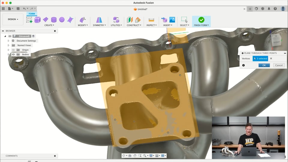
| 10:44 | What I wanna do is create a datum plane on this top surface here. |
| 10:49 | And we can do that usually here with our plane construction tools. |
| 10:53 | And using the plane through three points tool would be a good way to do this. |
| 10:57 | But you'll see that we can't actually click any points on the surface of the mesh in this case. |
| 11:04 | A little kinda workaround here is to go into this create forms toolbar. |
| 11:08 | And that basically kinda converts our mesh over so we can use this plane through three points tool and then on a nice flat planar surface like that we can select three well divided points on the surface and that will just fit a plane to that surface as we can see there. |
| 11:31 | And we'll just click OK and then we'll finish form. |
| 11:33 | So, now we have a nice plane on that surface there. |
| 11:37 | What we'll do is we'll jump into the mesh toolbar. |
| 11:39 | This is probably one of the better tools in Fusion for working with mesh files doing reverse engineering or scan based design for that matter. |
| 11:49 | So, this is creating mesh section sketches here. |
| 11:53 | So, if we select the mesh body that we wanna create the section through and then we'll select the section plane, which is going to be the plane we just created. |
| 12:04 | We can see these kinda burnt orange color here is where that plane intersects the mesh body it's creating a profile. |
| 12:12 | It's not a very good profile in this case because it's right on the surface of that flange. |
| 12:18 | But if we just pulled that back down slightly into it we can see that we get a much better clearer profile there of the flange. |
| 12:28 | So, what I'm going to do is I'm just going to set this distance here to negative 0.5. |
| 12:34 | So, we get a nice clear cut through the part before these kinda ports here start to taper too far and change the shape from the ports of the actual flange. |
| 12:47 | And we get some clear kinda profiles there of the mounting holes and also the outside of the flange. |
| 12:54 | And I'm just going to click ok there. |
| 12:57 | So, now we have those features added to our timeline here. |
| 13:01 | What I'm going to do is this is the mesh section feature here and then this is the sketch that it's created. |
| 13:07 | I'm just going to jump back to that and hit Edit Sketch. |
| 13:11 | Then for clarity I'll just hide the bodies, which will hide the mesh and then I'll also hide that construction plane just so we can see our profile really clearly. |
| 13:22 | Now, this is the second step that goes along with creating the mesh section sketch, which is fitting curves to the mesh section. |
| 13:30 | And then what we're going to do is start by fitting some circles to the mesh section. |
| 13:36 | And basically if we select the kind of circular features here it'll do its best to fit a circle to those. |
| 13:45 | We can see the max curve deviation here being 0.1 or so and the smaller that value is, the tighter it can fit a curve to that or fit that circle to that profile. |
| 13:59 | So, we're just going to hit ok on that for now. |
| 14:02 | And we're going to highlight those and set them equal and then we'll also just dimension them. |
| 14:09 | And we're going to make them 10.5mm. |
| 14:12 | What we could do in this case is if I had my verniers here, could have actually measured the physical part as well. |
| 14:22 | But pretty happy that 10.5 is probably appropriate, because it probably uses M10 hardware. |
| 14:31 | So, what I'm going to do from here in this case is again I could take physical measurements from the part to back that up, but I'm just going to kinda trust the 3D scan in this case because it's probably fairly accurate. |
| 14:46 | I'm using quite a quality scanner doing this. |
| 14:48 | Another way you could go about this is this is probably a standardised flange that's used in this case and there's probably a spec drawing for this that we could copy as well. |
| 15:00 | But I'm just going to work solely off the scan data, I'll just turn that 3D sketch preference off. |
| 15:07 | Wait for it to load. |
| 15:11 | And then what I'm going to do is just start working around and recreating this flange. |
| 15:16 | So, this is a little bit of a time consuming process, just drawing a line between those two hole centres, construction line again, just marking out some construction points that are going to help us to create this part. |
| 15:46 | And we always want the sketch to be fully defined, so we don't risk kinda losing things moving accidentally when we don't notice and then it kind of having a snowball effect to other issues that show up. |
| 16:02 | So, what I'm going to do is in this case I could dimension these from this kinda origin point here, what I'm going to do is I'm just going to lock down the position of the hole centres, so I know they can't move from the positions that they're in now because I'm pretty happy with them and their alignment to the mesh file. |
| 16:20 | And then what I'm going to do is basically make some other circles, take that construction preference off, make some other circles here concentric with the ones we've already created to start kind of sketching that outline for the flange. |
| 16:44 | And in this case it looks like it's kind of a little bit not as uniform as I'd expect but that's not going to matter too much. |
| 16:55 | So, I'm just going to start working around, we'll set the dimension of these circles, it should be about 20mm. |
| 17:04 | And then now what we're going to do is start tracing the outside of the part. |
| 17:10 | And you can match it perfectly to the mesh profile if you want. |
| 17:16 | In this case we're just going to do what we think the original design intent for the part should have been. |
| 17:26 | Another way you can do this is of course with this fit curves to mesh section thing and then we can use the line tool here as well and we can click points on the mesh section and then that will create a line like that. |
| 17:42 | I actually want that one to be parallel to those two. |
| 17:47 | And I'll fit those points there. |
| 17:52 | So, I'll just dimension that line up at maybe 7 looks about right. |
| 17:59 | Similar thing here. |
| 18:04 | And then we'll use a fillet tool in a moment to come in and round those edges. |
| 18:14 | And I'm just using the constraints there to set those tangent at those connecting points. |
| 18:20 | What we're going to use is the trim tool to remove the parts of the profile that we don't need. |
| 18:29 | Just a matter of clicking those parts. |
| 18:34 | We can click and drag through as well if we want. |
| 18:37 | We can also grab the fillet tool now. |
| 18:40 | And round those corners by looks like about 15mm radius. |
| 18:54 | Seems to match the scan pretty well. |
| 18:59 | So, that's all fully defined except for these lines down here. |
| 19:04 | So, I'm just going to drag that to see what the issue is. |
| 19:07 | I'm just going to make that line co-linear with that. |
| 19:11 | So, it lines up with those centers. |
| 19:13 | Then the only thing left to do now is the ports here. |
| 19:19 | So, let's start working through that. |
| 19:22 | Just kinda work out these quadrilateral shapes I guess there. |
| 19:34 | Start to dimension things in a moment, kinda drag them into alignment. |
| 19:42 | So, I think these two edges are parallel. |
| 19:48 | And start to square everything up. |
| 20:02 | Starting to look pretty good. |
| 20:10 | So, we'll start putting some dimensions on here to fully define this. |
| 20:15 | So, we don't end up with any issues. |
| 20:44 | And looks like those two. |
| 20:50 | There's a constraint on there that was preventing that. |
| 20:53 | So, what I'm going to do. |
| 20:57 | I'm going to line that up there. |
| 21:03 | We've got a little bit of an angle there. |
| 21:11 | What I'll do is I'll base that off the whole center there. |
| 21:14 | Make that. |
| 21:23 | It's a little bit of a time consuming process, but we'll get there in the end. |
| 21:31 | It's a bit much. |
| 21:38 | And. |
| 21:47 | Try to get these diagonal lines here locked in. |
| 21:51 | Oh not 28, meant 48. |
| 21:55 | And this one probably be. |
| 22:00 | But at least 26 maybe. |
| 22:04 | There's a few different ways you can go about this as is the case for most CAD things. |
| 22:11 | But that looks pretty good in that case. |
| 22:13 | So, what I'm going to do is I'm just going to grab the fillet tool and start to. |
| 22:18 | Oh I didn't get the fillet tool. |
| 22:20 | Yes I did. |
| 22:22 | Round those corners now. |
| 22:24 | It looks like about an 8mm radius seems to do a pretty good job. |
| 22:43 | Now, we've got a fully defined sketch for our flange profile. |
| 22:47 | So, we'll just hit ok with that. |
| 22:51 | And one thing to remember is that compared to the surface the actual sketch flange there was about half a millimeter. |
| 22:59 | Well it was exactly half a millimeter further down as we created that mesh section sketch. |
| 23:04 | We dropped it down to get a clear profile there. |
| 23:07 | So, what we're going to do now is we're going to create an extrude of that. |
| 23:13 | We're going to start the profile plane and offset. |
| 23:16 | Let's just make sure we're going in the right direction. |
| 23:20 | Yeah, 0.5mm further up. |
| 23:23 | And then the distance here we could create another plane on the back of the flange there. |
| 23:30 | But I'm pretty sure that looks about 10mm thick. |
| 23:33 | But that needs to be negative 10 to go in the other direction. |
| 23:39 | We'll just hide the mesh body. |
| 23:45 | Looks like maybe closer to 12mm thick there. |
| 23:50 | Of course, if I add my verniers I could just check what it was in the real model. |
| 23:54 | That's 10 and then we can just hit ok there. |
| 23:57 | And we can see that we've created that flange. |
| 24:00 | So, basically, I'm not going to go through the whole process of doing this for every part of it. |
| 24:05 | And what I'll do is I'll skip over to another model that we are working on in the 3D scanning course. |
| 24:13 | And show you how the rest of the part was done to kind of get from the stage that we've got here. |
| 24:19 | Over to the final part. |
| 24:21 | So, give me a moment to just find what I need to. |
| 24:35 | So, in this case what I did was extracted some of these entities in the PeelCAD software. |
| 24:41 | And then transferred this directly over to Fusion. |
| 24:46 | So, if we just roll back the timeline here you'll see some of the processes that I went through to create the part. |
| 24:54 | We'll just show the original scan. |
| 24:56 | So, it's the same scan. |
| 25:00 | I worked through here, created a sketch for the flange onto the cylinder head. |
| 25:06 | Same thing here, created a sketch for the turbo flange. |
| 25:13 | And then extruded both of those profiles to create these two bodies here. |
| 25:18 | And then I had two flanges basically floating in space. |
| 25:22 | And one of the features that we can use in Peel CAD or some other reverse engineering software as well. |
| 25:29 | Is to create centre lines for kind of pipe sections. |
| 25:34 | And that goes a long way in this case. |
| 25:37 | Let me just see if I can turn those on so you can see there. |
| 25:41 | That is the centre line following down runner one. |
| 25:45 | And then two, three and four. |
| 25:48 | And basically what I did was created another sketch using those. |
| 26:12 | Another sketch there with all those centre lines fully mapped out. |
| 26:16 | And then what I was able to do was create, use the surface loft tool there to create four lofts. |
| 26:25 | I'll just turn off the mesh so we can kind of see what we did there. |
| 26:30 | Show that last one. |
| 26:32 | Created four lofts. |
| 26:33 | So, basically what a loft is, is from the oval port profile on the flange there. |
| 26:40 | Through to this profile on the turbo flange. |
| 26:45 | And basically merges one profile into another. |
| 26:49 | And then also while I did that, if I just edit this here. |
| 26:53 | I used this guide centre line here. |
| 26:56 | And that was the centre line of the pipe there. |
| 27:00 | to kind of guide the shape of the pipe through. |
| 27:04 | Then from there it was basically a matter of just splitting the bodies. |
| 27:14 | If I give an example here, if I just jump back here, you'll see if we look down, I'll turn that sketch off so it's a bit easier to see. |
| 27:23 | If we look down the ports here we can see that this runner is blocking the path for this runner to come into the turbo flange. |
| 27:31 | So, the process from there on was using the split body tool and the remove tool to basically trim all those intersections out so we had kind of a nice merge, or yeah, merge collector I guess, where each of the runners would come in and meet with the other ones there. |
| 27:56 | And then it was just a matter of thickening those bodies up and then combining them in the end and then you could add some fillets to kind of round the sharp corners and reduce any stress concentrations as well. |
| 28:11 | And then what we end up with in that case is a recreated turbo manifold. |
| 28:19 | But a point to kind of add to that would be that this actual real part, as we can see under the overhead here, has a cast merge collector and flange as well. |
| 28:31 | And then they've had the kind of flange surfaces machined and the holes drilled as well. |
| 28:38 | And then the rest of it is a tubular manifold that's been fabricated. |
| 28:43 | And in this case clearly what I've modelled isn't the equivalent of this because these aren't circular sections through here. |
| 28:52 | So, this is an example of kind of changing the design a little bit to suit a different manufacturing technique. |
| 29:00 | So, in this case it was kind of looking at how we could change the design to be 3D printed from stainless as well. |
| 29:08 | So, it's not always a case of just perfectly recreating the part to make it in the same method because clearly if we wanted this part it wouldn't be worth our time to redesign it and make it ourselves, we'd just buy the part from the actual manufacturer who create a quality product already. |
| 29:28 | Again before we move onto the next topic, I'll just say if you have any questions on any of these processes, feel free to ask them in the chat and I'll do my best to answer them at the end. |
| 29:42 | So, the next topic we've got is scan based design , which as I discussed earlier is basically using our scans as a reference to design new parts. |
| 29:51 | And there's a few different kind of ways we can go about this depending on how many scans or components we're going to use. |
| 30:00 | So, I'll just give a quick example of two of those different approaches. |
| 30:06 | So, let me just open up a new file here, close those old ones so they're not slowing us down. |
| 30:17 | What I'm going to do here is I'm just going to insert another mesh. |
| 30:22 | And this one we can see we have this Volvo 16 valve scan. |
| 30:26 | And if you are regular at our webinars, you might have heard me talk about this Volvo engine before and some of the work I'm helping my brother do on it. |
| 30:35 | But this is a scan that I took with our Peel 2-S, which is our old scanner. |
| 30:40 | And we can see it's not too flash around some of these flange surfaces here compared to the Peel 3 that we just used. |
| 30:50 | So, might be a little bit of issues there but we can basically do the same thing. |
| 30:56 | So, in this case we're not going to try to recreate the cylinder head. |
| 31:00 | That's possible, but it's not the intention here. |
| 31:05 | Another way that we could look at this would perhaps be recreating this flange surface here so we can create an intake manifold for the part and maybe that is something that we could get machined from aluminium and then weld tubing onto that. |
| 31:25 | If we just model the flange with the start of the runners, maybe we could transition the ports here from this kind of slot or oval shape into a circular profile and we could machine that into the flange as well or we could get it metal 3D printed as well. |
| 31:46 | So, the process here would very much be the same. |
| 31:49 | We've just imported or inserted the scan into our design, we'd jump into our form tool here, we'd use the plane through three points tool and this is the way we do it if we don't have reverse engineering software like PeelCAD and we can create a plane on that flange surface there, click ok , finish that, jump into the mesh toolbar, create a mesh section sketch through this mesh body with this plane here and then we can drop that down into the part, half a mil or so, so we start to get a nice section where that plane intersects the mesh body and again jump in here, edit the sketch, hide the body, delete that and then we can start working around here, fitting curves to the mesh section profile and start to recreate the flange. |
| 32:55 | Basically, the same method that we just used for reverse engineering. |
| 33:01 | So, that's the case if we're only working off a single part, a single scan in this case we can create a new design off but in many cases we use our scans slightly differently. |
| 33:15 | So, I'm just going to close this and we'll look at another example of a case where we've basically used multiple scans at once and other components that we've modelled in essentially an assembly. |
| 33:33 | So, I'm just going to get that part open, bear with me. |
| 33:43 | So, we'll start with this here, so this is a KP61, an old Toyota Starlet that Brandon's building for a rally car project and this is a scan I took kind of off the front end of the car here with all the suspension pickup points and he's got the front end that he's using mounted in there as well so I can avoid that while we work on designing some front suspension for this car. |
| 34:09 | So, in this case we want to use this scan, but we also want to use other components while we're designing the suspension and kind of create more of an assembly. |
| 34:21 | So, what I've done here is I've, well transferred the scan over from our PeelCAD software and then this has got all the features from the PeelCAD software in it with the entities that we extracted from it and just done a little bit of work here as well to find the centre points of the strut tops and also created a sketch on the bottom here and this is kind of the key point from here on. |
| 34:55 | So, created in the PeelCAD software, we basically made a plane on the bottom surface of the chassis rails there just like what we'd do with our plane through three points tool from our forms toolbar. |
| 35:09 | And then once we have that plane, basically used a mesh section to find the centre points of these mounting studs for the subframe. |
| 35:23 | And then from that I was able to create a bit of a 3D sketch here, which you can kind of see, if I just hide the scan, , which basically finds the centre of the scan and then I was able to create some planes through that as well. |
| 35:42 | So, we've got a plane that's flat to the bottom of the chassis rails, one that's just in between the two studs there in that kind of forward back position and then one straight down the centre line of the scan as well. |
| 36:01 | Once I had those, from there I jumped over and I inserted that into another design file and this is what I'd call the main design file or the assembly in this case. |
| 36:14 | Might just take a minute to open up. |
| 36:17 | And then basically, so what I'm doing is I bought that scan in there, I've saved it as its own component and then I've inserted it into another file here. |
| 36:27 | So, I've got this same scan bought in here as this component here, which is the first one. |
| 36:35 | So, basically what I did there was I inserted the scan in and then I aligned it with the origin there. |
| 36:44 | So, the origin planes aligned with those construction planes that we made. |
| 36:52 | So, we've got this scan of our chassis sitting smack bang in the middle of our workspace and it's nicely aligned with our default coordinate system so when we start to create parts and do sketches and things like that, we can use things like our horizontal and vertical constraints to lock everything in with that coordinate system and it just helps us create everything nice and square and use those constraints to keep things tidy. |
| 37:20 | So, once I had the position set, I just created a rigid group there just to lock the position of that down. |
| 37:28 | And then I began moving through the parts. |
| 37:31 | So, there you can just see I've inserted the upright, which is also another part that we were working with in our 3D scanning course. |
| 37:41 | This is just an S14 upright , which we're trying to basically design into the suspension for the Starlet, so we can use the S14 upright, often Nissan Silvia or S14. |
| 37:54 | And we got the braking package and things on there as well or just some parts that we basically designed during the 3D scanning course. |
| 38:02 | Then I have a scan of the 15 inch rally wheel that we're using, that Brandon's going to be using on the car as well. |
| 38:11 | So, you can see it's just sitting in the middle of the chassis there, just basically moved it out to the approximate position it would be in and then started setting up some joints between the parts just to basically simulate how they'd fit and function together. |
| 38:32 | And what I have here, I'll just skip forward a little bit more. |
| 38:40 | So, about here is just a very basic model of a coilover that he's looking to possibly purchase for the car. |
| 38:50 | That's just like a gravel rally coilover there that will fit to the S14 upright and I've just got that in, set it up with a ball joint at the top here, a bit of a slider here to simulate the damper movement and then this is just fixed down here rigidly to the upright as it would be in a real situation. |
| 39:10 | So, we keep progressing through, I've dropped in a potential steering rack that could be used in the car, it's just a Woodward Motorsport rack. |
| 39:18 | Kind of positioned that very roughly for now where I think it should go, so it's under the engine and pointing kind of up into the steering column space. |
| 39:30 | We just keep moving on. |
| 39:32 | We've got examples here of bringing in multiple components and scans as well. |
| 39:37 | That's a scan of the steering rack, this is a scan of the S14 knuckle with some really basic solid features built into it. |
| 39:50 | And then we've got obviously the scan of the chassis as well. |
| 39:54 | And as we keep coming through, I'll just flick right to the end. |
| 39:58 | Again this is just in the planning out phase, this is definitely not how things are going to look. |
| 40:04 | But I just created a basic sketch to put some points in space for the suspension pickup points, just to kind of lock everything in. |
| 40:14 | This is something I just did last night. |
| 40:18 | And I've got some joints set up here just for ball joints, got some structure here for the outer tie rod end as well and we can just start planning out kind of some points and space and then once I get this a little bit more suitable where this lower control arm is actually nice and flat, we don't have positive camber on this arm and I can adjust the length of this tie rod end here to get the tow closer to zero, cos it looks like it's massively towed out at the moment. |
| 40:54 | Then I can start to take measurements off this and then transfer those into a software like Optimum G to be able to analyse the suspension geometry and kind of plan out what's going to work well for this car. |
| 41:07 | And then after that we can come back, we can modify where these points are in the CAD software so we know where all the points need to be and then it's basically a matter of connecting the dots, designing a subframe, designing a lower control arm and things like that around those points once we know where they need to be so we get the suspension kinematics in the correct place as well. |
| 41:30 | So, the key point to remember here is that if you're working with multiple scans or components to do scan based design, in Fusion at least, it's better to set them up as external components, their own components and then insert them into a design file, a main design file like we have here or an assembly, kind of build them up so we can use joints to define the relationships between the parts. |
| 42:01 | And then that way we can kind of control how they fit and function together so it's closer to the real thing. |
| 42:07 | If we just went about it where we're working in this file here and we just kept inserting the scans into this, we wouldn't be able to set up the joints or control the relationship between them as well and you just end up with a lot of headaches if you do it basically in that case. |
| 42:26 | So, having them all as individual components like this is definitely the way to go from my experience. |
| 42:32 | So, yeah we'll basically leave it at that for this webinar. |
| 42:38 | Of course, if we were going to do some scan based design or reverse engineering with some surface modelling of body panels or something like that, then there would be, that's kind of a whole other side of things that's quite a little bit different to this mechanical design. |
| 43:00 | InUse is really a completely different tool set as well. |
| 43:04 | So, what we're going to do is we're going to cover that in a coming module as we get more into those things. |
| 43:11 | But a lot of what we've covered here has been covered in our 3D scanning course, which should be out and available by the end of the year. |
| 43:22 | So, I'd recommend if you're interested in learning how to do a lot of this stuff and getting the full kind of rundown on how to do it step by step, then definitely keep an eye out for that course by the end of the year hopefully. |
| 43:37 | So, what I'll do now is just jump into the chat and see if I can answer a few questions. |
| 43:46 | So, Phil asked "Have I used Geomagic before?". |
| 43:50 | No, I haven't actually used Geomagic before, but I am familiar with it. |
| 43:54 | I've seen it used, I just haven't had access to the software myself, which a lot of people haven't, it's a very expensive piece of software. |
| 44:03 | For those who aren't familiar, I've mentioned PeelCAD quite a few times in this webinar , which is if you're using a Peel3D scanner then PeelCAD is kind of their reverse engineering software. |
| 44:16 | Some of the other manufacturers, I think Einstar has VX model or maybe I'm getting that confused. |
| 44:24 | But Geomagic is basically a software that's been developed by 3D Systems, which is one of the big players in 3D printing actually. |
| 44:33 | But Geomagic Design X I think it's called is a reverse engineering software, which does a really good job of extracting entities and giving us all those features to be able to reverse engineer parts. |
| 44:48 | So, a lot of that is just, it's able to identify the different forms and geometry of the part and pull features out of it. |
| 44:58 | But Geomagic is actually quite a strong CAD modelling software in itself, so you can do a lot of the work inside Geomagic and then transfer directly to Solidworks definitely but maybe Fusion as well from there. |
| 45:13 | Although no, I'd love to use Geomagic, I don't have access to it. |
| 45:19 | So, RT, "Has Fusion improved its efficiency with mesh files? I've only ever had Fusion. |
| 45:26 | I designed a whole turbo program and suspension program with the EinScan Shining3D and Fusion. |
| 45:35 | Prusa and Bamboo Slicer was easier to use and manipulate.". |
| 45:41 | So, I actually find Fusion to be really good with mesh files and scan data. |
| 45:48 | That depends on what you're comparing it to. |
| 45:53 | I don't really use Slicers too much to manipulate meshes. |
| 46:00 | I generally do most of that and in our case we've got a Peel scanner so in the Peel operating system or in PeelCAD or if I bring it into Fusion 360 there's quite a lot that you can do in Fusion as well, I find with meshes. |
| 46:14 | If I just jump back over to Fusion here, go to that mesh we have into the mesh toolbar. |
| 46:21 | A lot of these modification tools here are quite good for cleaning things up and doing some stuff like that but we can also do remeshing from here as well and use the tools that I just covered in the webinar so hopefully that shows a little bit more insight into that. |
| 46:40 | I find it to be quite good, Fusion to be really good with meshes, but I'm sure compared to a 3D scanning or reverse engineering software that's more tailored towards working with meshes I'm sure they're another step up again depending on what one you're using. |
| 47:01 | Some of the 3D scanning software that comes with the more cheaper options like our RevoPoint Range here, a lot of the features in the mesh editing software for those are very limited. |
| 47:20 | Fusion's a long way above that, but yeah some of the things like Peel CAD for example gives you quite a lot of flexibility over that again. |
| 47:31 | Phil "How well does Peel CAD do for the centreline finding extrapolation?". |
| 47:37 | I haven't used it heaps, but I used it on this part and from what I can see for making, like tracing the centreline of an exhaust or something like that or intercooler plumbing or maybe even, brake lines might be too small, but other plumbing in the vehicle, from what I can see it works really well. |
| 47:59 | From my experience. |
| 48:03 | What I will say is, I don't have that example open anymore. |
| 48:09 | When I used it for doing this part here you can basically pick up the centreline of this part and control how far along there the centreline goes. |
| 48:21 | And what I ended up doing was basically setting it so the centreline would kinda only do the middle 70% of the part so it would stop before it got down to the flange here and before it got into the turbo manifold here. |
| 48:41 | Because if you're working with a loft or a sweep, a loft in our case, then the centreline needs to go straight through the centre of the actual profile that we're using and it's very hard, that's obviously not going to be the case, it's not going to go perfectly through the centre. |
| 49:04 | So, again I just had it pulled back slightly from either end and then I just used another sketch and kinda traced that line and then had that come off as a spline down to the centre of that part so I could control that a little bit better. |
| 49:20 | That's kinda the only issue that I had with it, it's just a simple workaround really and it worked fine, it's pretty easy to do. |
| 49:28 | Yeah, generally, I've found that if you have a nice scan of quite, a clearly cylindrical body, then finding that centreline of the pipes is pretty easy and it does a really good job. |
| 49:41 | If you were like scanning where a stock exhaust went and you wanted to match the same routing of the exhaust under the chassis and you had quite a good scan of that, then you could find the centreline of that and then you could get, design a new exhaust with slightly different components or obviously a larger tubing and then you could get that mandrel bent or something from there just by using that centreline or exporting a step file, that would be a quite good way to go about it I'd say. |
| 50:18 | But yeah, that looks like all the questions. |
| 50:21 | So, again if you're interested in this topic, we've got our 3D scanning course coming out hopefully pretty soon in the next few months. |
| 50:30 | So, keep your eye out for that and yeah we'll be back next week with another webinar, and more updates on the SR86 so we'll see you then. |