363 | How to Design a Brake Calliper Bracket in CAD
Summary
Brake calliper conversions and upgrades are common place in project cars, but you shouldn't let yourself be limited to off-the-shelf options. In this webinar we'll show you how to design a brake calliper bracket and what you need to consider to mount the calliper in the perfect position.
| 00:00 | Hey team, Connor here from HPA and welcome to another one of our webinars. |
| 00:04 | So, today we're going to be looking at how to design a brake caliper bracket in CAD. |
| 00:09 | So, first of all we're going to look at a few different methods of doing this in CAD, basically with or without 3D scans. |
| 00:17 | Basically, it's kinda easier if you have the 3D scans, but obviously if you don't have 3D scans then we'll show you an alternative as well. |
| 00:26 | And we'll also discuss what we need to keep in mind when designing a brake caliper bracket in terms of our actual braking system function to make sure we get the best performance and also reliability and don't kinda cause any issues for ourself as well. |
| 00:42 | So, this is going to be kind of combining the topics of our CAD course and our brake course and also our upcoming 3D scanning course, which should be released kinda by the end of the year. |
| 00:55 | So, first of all, why would we want to design a brake caliper bracket? Brake caliper and disc conversions and upgrades are really commonplace in performance automotive or motorsport applications because the original factory brakes that came on our cars come with a lot of compromises and they're generally going to be one of the first things to give us issues when we get out on track. |
| 01:19 | So, we often upgrade the calipers and also the discs for more thermal capacity, for stiffer calipers, lighter calipers as well, often with more pistons for better force distribution on the brake pad. |
| 01:38 | And also bigger pistons obviously for more power as well. |
| 01:42 | And we don't want to limit ourself to what the off the shelf options are for big brake kits. |
| 01:49 | We've actually covered this in a previous webinar talking about how to choose brake calipers when you're upgrading. |
| 01:56 | And covered some of the issues with some of the big brake kits that are kinda sold and aren't actually going to be a very good fit for our application. |
| 02:07 | It's pretty common for cars that are modified quite a lot to be quite different from the factory configuration and sometimes an off the shelf kit that's been designed for the factory vehicle is no longer suitable for our application. |
| 02:23 | That's not to say that some of these brake discs are really good, it really just depends on the car and what we're buying as well. |
| 02:33 | And some old cars as well or some really kinda different applications, it can be hard to find what you need so obviously it's good to be able to design it yourself. |
| 02:47 | So, let's get onto some considerations around our braking system. |
| 02:52 | We're going to start with an assumption that you're trying to fit the correct size brakes to your car and you're not doing something completely ridiculous. |
| 03:02 | And for example fitting something like this big Brembo over here that is designed for a Range Rover and you're trying to fit that onto, I don't know, a Honda Civic or something. |
| 03:17 | Obviously, it'll work and you might think it looks cool and big brakes are really cool, but the size of it and the size of the pistons, it's just not going to work very well. |
| 03:27 | It's also designed for a really large brake disc that isn't going to fit inside any reasonably sized wheels for a smaller vehicle as well. |
| 03:39 | The other thing that we need to keep in mind is that the caliper and the disc size are considered together. |
| 03:48 | So, basically what I mean for that, if we look at this Endless Mono 4R under the overhead here, this design where you can kinda see this sweep coming through here is designed to suit, probably be optimised for a certain disc diameter. |
| 04:08 | But they will have on the supplier's website a kinda recommended range that the disc needs to sit inside. |
| 04:18 | So, maybe for this example it might be between a 280 mm disc diameter to a 340 or something like that. |
| 04:28 | I'm not sure exactly in this case. |
| 04:31 | And obviously if we're using a disc much smaller than that, then we're going to have some issues with trying to line the disc up with the pad, which we're going to cover soon. |
| 04:41 | Or if it's really large, it's just not going to be ideal basically. |
| 04:46 | So, we want to make sure that we're choosing the right size diameter disc and caliper together. |
| 04:52 | And the other thing to consider there as well is the actual thickness of the disc that we're using in the caliper. |
| 04:59 | So, these allow for quite a wide disc as you can see through there. |
| 05:06 | Some calipers will have a much narrower gap here and obviously allow for a smaller thing. |
| 05:12 | So, like the diameter, there'll be a range that the caliper is designed to work with. |
| 05:18 | It'll be the same for the thickness, maybe it allows for something between like a 22 mm to a 30 mm thick disc. |
| 05:26 | But we'll get into that a little bit more soon. |
| 05:32 | So, the important things when we're actually designing the brake caliper bracket is the caliper's position relative to the disc. |
| 05:40 | So, if we'll look at this one here. |
| 05:47 | Might be better to show this down here actually. |
| 05:50 | I didn't actually bring a brake pad with me. |
| 05:55 | But essentially what we want to do is we want to position the caliper relative to the disc so that as the pad is sitting on the disc, the top edge of the pad lines up with the top edge of the disc. |
| 06:10 | That's going to basically mean that if it was overhanging, we would end up with a nasty sharp edge on the pad or a nasty sharp edge on the outside of the disc. |
| 06:20 | Neither of those are what we want for keeping the temperatures down, wear rate and also something called compliance as well. |
| 06:30 | We'll get into compliance a little bit more in a moment, but basically if we try to line the edge of the pad up with the outer edge of the disc, that's going to be what we're aiming for and anything within plus or minus a millimetre or so of that is acceptable, but we should be able to get it bang on if we're designing these parts in CAD. |
| 06:53 | The other thing to consider is having the pads parallel to the disc and what I mean by that, this might get kind of difficult to show under the overhead. |
| 07:04 | If we're positioning the caliper over this, then we need to make sure that the pads are going to be running parallel with the disc. |
| 07:15 | So, essentially if you imagine the caliper was on an angle like that, then they're obviously not going to run parallel, the other way is if the caliper is tilted on an angle like that, they're not going to run parallel either. |
| 07:31 | And what we end up with there is an issue where basically the pistons on either the front to the back or either side are moving at a different amount basically and the pads kinda get on an angle as they take up on the disc. |
| 07:51 | And not only does that put a side load on the pistons, which means that they don't slide properly and you can damage the seals or the caliper body as well but it actually causes something called compliance and compliance is basically a lack of stiffness in the braking system where if we press the brake pedal a certain amount, then we kinda have to press it more to some extent, because some of the force from the pedal is basically reduced in inefficiencies in the system like that. |
| 08:26 | So, that could be the caliper stiffness, the caliper just flexing and that's essentially what we're introducing there where we have the pads kinda taking up on a funny angle. |
| 08:37 | So, we want to avoid that, have them running parallel to the disc to ensure that we reduce the issue of compliance. |
| 08:46 | So, the next thing, might be best to just show this in this direction, I'm in the main camera. |
| 08:55 | As the, it'll be better to show it with this other one, sorry, bear with me. |
| 09:04 | So, you can see here that I'm holding the upright as it would be positioned in the vehicle with the strut mount going upwards and we can see that the caliper on the side is actually in a near vertical position. |
| 09:20 | Actually as the caster of the car, the front suspension goes back like that, it'll be pretty much bang on vertical. |
| 09:27 | And the reason we want that is basically it comes down to bleeding the air out of the caliper. |
| 09:33 | So, the caliper at the top here has these two bleed nipples, I'll show this under the overhead, and it's important that these are facing upwards so we can bleed the air out of the system, because obviously the air rises up through the fluid and out the top. |
| 09:52 | If we have the caliper positioned sideways like this, then it's going to be very hard to bleed any of that out and especially if it's up that way, it's going to be near impossible without vacuum bleeding it out of the system. |
| 10:07 | Most calipers like this will have a bridge around one side and then two bleed nipples like that, or maybe just one on one side, depends really on the caliper. |
| 10:23 | And the caliper left to right will basically be the same part, you'll just be able to change the bridge and the side of the bleed nipples on it to the other side as well. |
| 10:32 | So, that's kind of the third and final thing that we need to keep in mind. |
| 10:36 | So, just to kind of recap those, lining the edge of the pad up with the edge of the disc, keeping the pads parallel to the disc, basically keeping the caliper nice and square to the disc and then keeping the caliper in the correct orientation to allow for bleeding. |
| 10:55 | As we discussed, compliance as well, and trying to avoid a lack of stiffness, if we buy a nice monoblock caliper like this that's really stiff, we obviously don't want to design a bracket that then mounts that to the upright and is not very stiff at all and we kind of lose all the stiffness of our nice caliper just through the bracket because it's really flimsy or something like that. |
| 11:23 | But at the same time we generally make our brackets out of aluminium to keep the weight down as well. |
| 11:31 | So, kind of few things to consider there as we get into designing the parts, which we're going to look at in CAD in just a moment. |
| 11:39 | Before I get into that, if you have any questions come up during any of this process, feel free to ask them in the chat and I'll do my best to answer them when I get to the end of the webinar. |
| 11:57 | Just open one more thing before I forget. |
| 12:04 | So, what we're going to do is start with the method that is essentially not using 3D scans. |
| 12:10 | So, if we're not using 3D scans, well essentially I'd use a 3D scan of the brake caliper if the supplier wasn't able to give me a model in the form of a set file or something like that. |
| 12:23 | And also generally I'd use a scan of the suspension upright as well. |
| 12:32 | Because those are the two parts that we're really trying to connect. |
| 12:36 | And then rather than using a scan of the brake disc, often I would just create a model of that. |
| 12:43 | But I'll show you all this in just a moment. |
| 12:48 | So, this here is actually a model that I created of the Wilwood Dynapro single piston caliper that's on the back of our CRX. |
| 12:58 | I'll just hide this sketch for a moment. |
| 13:01 | So, it's actually a really basic model. |
| 13:05 | And the way I created this, if I jump back to the canvases, hide that body. |
| 13:15 | So, if we look at the front here, this is just screenshots that I took off the Wilwood website for them showing the specifications of the caliper and all the dimensions as well. |
| 13:27 | And then basically I just apply them to the default planes, the left and the right planes there. |
| 13:37 | So, I have a look straight on of the front there and then also the side on view as well. |
| 13:45 | And then from there I can just basically sketch on those planes and use those as a reference to start designing the parts. |
| 13:53 | If we just step back and kind of show the process of how this was modelled. |
| 13:58 | Start off with a sketch. |
| 14:01 | Just kind of tracing that outline. |
| 14:03 | And you'll see that this doesn't actually align with the canvas. |
| 14:07 | That's just because this mount centre was given in a table. |
| 14:13 | So, I just matched that to our actual caliper. |
| 14:17 | And then it's just a matter of slowly moving through and starting to kind of bring the design to life. |
| 14:26 | With some extrudes from that sketch. |
| 14:29 | Matching the dimensions of the actual part given off those drawings. |
| 14:36 | I did this quite a while ago so I can't remember exactly how I did it. |
| 14:41 | But yeah, stepping through to the point where we actually basically have the caliper modelled without having one on hand just based off those canvases that were supplied on the website. |
| 14:55 | This last point here is a really important point when we get into actually assembling the parts together in CAD. |
| 15:03 | And that in this case is actually using this sketch here showing the position of the disc. |
| 15:10 | So, that's lined up bang on in the middle of the caliper there. |
| 15:15 | And also I'm not sure exactly what diameter that is. |
| 15:21 | 260mm just to match the diameter of the disc that we were going to be running on this car. |
| 15:29 | And then also here that's basically just lined up, if I hide the body it might be easier. |
| 15:37 | I have sketched in the position of the brake pad in there and then you can see that the disc is lined up with the top of the brake pad. |
| 15:45 | Just to make sure that we get this in the correct position. |
| 15:49 | And then as we bring this into our assembly, which I'll show you the equivalent of soon, then we can use that to position the caliper over the disc, so the disc runs straight down the middle of the caliper. |
| 16:06 | I'll just leave it there for that one for now. |
| 16:09 | So, basically with this we could then take some measurements off our suspension upright, if we had the real part, and off those mounting lugs and then be able to understand where the, if we had a brake disc on the car already, we'd be able to understand the distance from those lugs on the upright to the brake disc and then we know then the position from the brake disc shown off this sketch to the lugs on the brake caliper. |
| 16:44 | So, that's how we'd be able to set that up without 3D scans anyway, but it's obviously a little bit more tricky. |
| 16:50 | Luckily for us we actually have a 3D scanner. |
| 16:55 | So, I'm just going to show you a kind of method here and then you'll be able to basically go backwards from this to understand how that would work without a 3D scan, if that makes any sense. |
| 17:08 | I'm sure it'll make more sense in just a moment. |
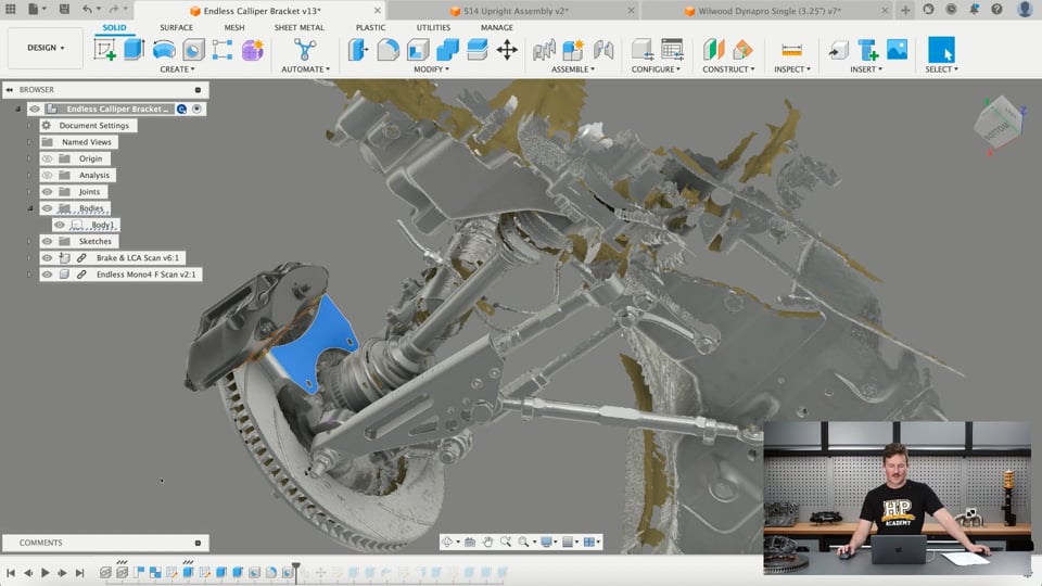
| 17:10 | So, this is a 3D scan taken off in the wheel well of the vehicle and in this case I actually had the brake disc fitted as well. |
| 17:22 | And then I'm just going to hide those bodies so we can see here on the back of the upright here we have the brake caliper mounts. |
| 17:31 | And what I did in this case, if we edit this part. |
| 17:40 | So, I've set up a plane on the back of those lugs there and then from that I was able to model two just solid bodies. |
| 17:55 | So, just little bosses basically, little cylindrical mounting bosses to match where those parts are. |
| 18:04 | So, that's basically the setup of the 3D scan component and then I bring that component into an assembly. |
| 18:11 | So, that's just an external component of that whole 3D scan. |
| 18:18 | And then I dump that into an assembly and just kinda line it up basically with the coordinate system there. |
| 18:25 | Then what I've got is, it's actually hidden at the moment, a 3D scan of the same Endless Mono 4 here and then I can bring that into the assembly as well and line that up in the correct position. |
| 18:45 | And I've just skipped something here but if we edit this part, we'll see here that on one of these sketches, the same thing here. |
| 18:59 | So, basically I created a mid plane in the middle of the caliper, essentially just by getting a plane on that front surface and the back surface or maybe it was on the surfaces between here and then find the mid plane there as well down the centre of the caliper and then from that, in the scan I actually had the brake pad still in the caliper and I've just lined up a circle matching the diameter of the brake disc that we're going to use with the edge of the brake pad there as well and then I've just projected that with this little purple dot you see. |
| 19:48 | This little purple dot you see is bang on in the centre of where the disc should be in the sideways position here so it lines up straight down the centre of the part and also in this position here so it matches the centre of that disc. |
| 20:04 | I actually did the same thing on the 3D scan as well, just creating a mid plane, I'll just finish editing that, a mid plane, so a plane on the front of the disc, a plane on the back of the disc and then use those to find a mid plane kind of halfway between them and then sketch on that mid plane and then find the centre point for the disc there and once I have those two points, then what I can do is when I bring the caliper in, I've set up a joint, which would be, ah not a joint sorry, I brought the caliper in and I can align the caliper using the alignment tools under the modify tab. |
| 20:51 | Basically, I'll drag this back a little bit to this point. |
| 21:00 | So, I've brought the caliper in, it's just floating over here and then the next step is just using the alignment tools there to align those two sketch points together and that basically will align our caliper in the right position. |
| 21:14 | And in this case, what I did was I just also dragged it around, if we look at it from the side, it's in essentially an upright position, close enough to vertical that we won't have any issues with bleeding and yeah, just rotated it around and it also provides the shortest path from these mounting bosses here onto the upright as well so we can make a nice stiff caliper. |
| 21:44 | So, we've got our kind of three things ticked off there where we know that the caliper is nice and square to the disc, we know that the outer edge of the pad is lined up with, I'll just hide those planes. |
| 22:04 | Lined up with the edge of the pad, sorry the edge of the pad is lined up with the edge of the disc there and we know that it's in a correct orientation that we're going to be able to bleed it. |
| 22:16 | Now, eagle eyed among you might notice that the bleed nipples are actually pointing down and we have the bridge along the top, that's just because I scanned the driver's side or right hand side in our case of the vehicle and I scanned the left hand caliper because the calipers are the same left to right, that's not actually an issue. |
| 22:39 | So, from there it's just a matter of really joining the dots together so we can design the brake caliper bracket. |
| 22:47 | So, I'll show you how I did that. |
| 22:49 | So, basically I've just sketched on the mounting lugs here on that plane and just kind of roughed out an outline for the bracket. |
| 23:01 | Then from there, just show the bodies. |
| 23:08 | I've just extruded that out to get the kind of rough shape and then created a sketch on the bottom of those mounting lugs there, then also extruded them out as these kind of cylindrical bosses. |
| 23:27 | And then just kind of cut that down to make the transition a little bit smoother as well. |
| 23:34 | And then if I hide the caliper, we'll be able to see, just put some threaded holes into the top of the part there. |
| 23:43 | And then also moving through, created some threaded holes for mounting to the upright as well. |
| 23:53 | The main thing, oh don't need to go to there, the main thing is really just making sure that we have the caliper set up in the correct position over the disc and then the actual modelling process from there is pretty straightforward. |
| 24:10 | It's just a matter of joining the dots really. |
| 24:13 | And then from there, like I said, I just modified this part very slightly by putting in these nut pockets in the back and then just so it was suitable for a 3D printed prototype. |
| 24:26 | And that's where we end up. |
| 24:30 | So, now I'll just move on to showing the other example we have here. |
| 24:37 | And don't mind the five stud hub and the four stud brake disc, I just haven't had the chance to change that over in the model just yet. |
| 24:46 | But it is going to be a four stud piece. |
| 24:50 | So, let's just jump back to here. |
| 24:56 | So, we've got no brake caliper bracket here. |
| 24:58 | So, basically what I've got is a 3D scan of the upright , which I've bored in and aligned with the coordinate system. |
| 25:09 | So, that's the upright there. |
| 25:11 | And then the same thing, created some planes on the back of it on the mounting points here for the caliper. |
| 25:19 | And then I've just modelled, find the ones, some little bosses here. |
| 25:28 | So, body 18 and 19 are just two little cylindrical bosses with nice surfaces that we can use to create our model where it's a little bit tricky working off the actual 3D scan surfaces itself. |
| 25:44 | But that is set up as a component inside this assembly. |
| 25:49 | And then we basically move forward from there to bring in other components. |
| 25:54 | We've got the hub coming in now and then we can set up a joint between those two. |
| 26:02 | So, they're in the correct position, I bring in the brake disc. |
| 26:07 | And then same thing, set up another joint here. |
| 26:11 | And we can see that I can rotate that so that's just kind of basically set it up as a revolute joint, the same as the real part would be. |
| 26:21 | Moving forward, bring in the brake caliper. |
| 26:26 | And again you'll see here, so on our brake disc, if I go to sketches, try to find the sketch. |
| 26:45 | So, that sketch there, let's hide some parts. |
| 26:53 | So, that sketch there is just right on the centre of the brake disc, in the centre, but the midplane between the two friction surfaces is also in the centre of the disc. |
| 27:06 | And then you'll also be able to see on the brake caliper I've done the same thing where I've got that point there, which is just marked out again by sketching a circle with the same diameter as the actual disc that we plan on using. |
| 27:28 | And then lining that up with the outer edge of the brake pad there and then I've just offset that into the midplane of where the disc would actually be in the centre of that caliper. |
| 27:44 | Then from there it's just a matter of aligning those two points and then just dragging that into the correct orientation. |
| 27:55 | If I turn those other parts back on you'll be able to see where it's going to be in a nice vertical position, or close to vertical to allow for bleeding. |
| 28:05 | And I've done the same thing again here where I have the driver's side spindle and I actually have the passenger side brake caliper. |
| 28:13 | Same thing, I've got the nipples pointing down and the bridge across the top but they're both the same so left or right it won't actually matter for designing the part. |
| 28:23 | And then I just lock those together as a rigid group so nothing can move and I'll show you then how I modelled the part. |
| 28:34 | So, if I just hide some of these sketches. |
| 28:42 | Just to keep things a bit clearer. |
| 28:51 | So, now we've got everything in the correct position and we have that aligned vertical, or vertical enough for bleeding and we have the disc aligned with the edge of the pad there and then the caliper nice and squared up with the rotation of the disc so we're not going to run into any compliance issues. |
| 29:11 | So, from here the next step was to sketch on the back of the mounting holes there and just map out some basic circles where the mounting points were and then just draw a bit of a shape to kind of connect them together and these are basically just projections of those mounting bosses and then some straight lines that are tangent to each one and then in this case I just needed to do a bit of an arc cos if we zoom in here there's a bit of kind of geometry that you need to get around on that side. |
| 29:45 | And then these other lines here, which you'll see in a moment is just as we create the 3D part we kind of needed some clearance around the mounting points on the caliper. |
| 29:57 | So, if we finish that sketch, the next step was starting to extrude the part and build out the body. |
| 30:04 | So, all this is is just an extrusion of the part of the sketch profile that we had there. |
| 30:14 | And then the next step was to just extrude the other parts and bring that up so we have some parts that actually mount the bracket in the correct position. |
| 30:28 | And in this case we just left those holes out as well, because we can mount from the back of the part with the hardware through into the threaded bosses in the caliper. |
| 30:39 | Then we created the threaded holes for mounting to the suspension upright and just a few more rounds to kind of finish off the part. |
| 30:49 | And if I just hide those parts we'll be able to see the finished bracket there. |
| 30:54 | Just has some round of the internal corners just to reduce any stress concentrations so we don't get our aluminium brake caliper bracket cracking. |
| 31:05 | And again I was just able to 3D print that part, it's pretty simple, just come into here, make, 3D print, select the part we wanna do, and I've got this set up so it'll send it directly to our printing application, which is Bamboo Studio in this case. |
| 31:25 | And it's as simple as, this isn't wanting to zoom correctly, anyway we'll do it from here. |
| 31:39 | Simple as laying it flat on the face and then just setting up the material over here that we want to use and the settings that we want to use as well and we can adjust some things around the strength of the part here. |
| 31:54 | Infill density, how fast it's moving, all these things. |
| 31:58 | Most of these here are actually default settings in this case that are just set up for this material inside the software and it's as simple as that. |
| 32:09 | We can just hit slice plate, so that just creates a kind of tool path here. |
| 32:16 | If we zoom in a bit we can basically simulate here how the 3D printer is going to build up those layers and then it's just a matter of hitting print plate and then that'll send it to the printer and print the part. |
| 32:30 | And that's basically what the entire process looked like for creating this part here. |
| 32:39 | So, the part that we see on the back here, just a 3D printed part. |
| 32:43 | Yeah, so we can check everything in the real world and make sure that we haven't missed out on any important considerations. |
| 32:52 | In CAD that is sometimes more obvious when you see the part in real life. |
| 32:56 | So, yeah, those are our exact parts and we can check that, I don't have the brake pads in there at the moment but we can just check that everything kinda lines up as it should. |
| 33:09 | And yeah, at the moment this is all just kinda done up loosely so it's not held together really properly and in good alignment. |
| 33:16 | But once I do that I'll be able to check that the edge of the brake disc here lines up with the edge of the pad. |
| 33:24 | We know this is in a good position to allow for bleeding. |
| 33:28 | And the caliper is also nice and square to the part as well. |
| 33:32 | Just to give us the confidence that when we go and get the part machined, get this brake caliper bracket machined, that we know it's going to all work as we intended. |
| 33:45 | So, hopefully that's just given you a little bit of insight into how to design something like that for a lug mount or axial mount caliper, or the likes of the radial mount caliper like our endless one here. |
| 34:01 | Just two different options. |
| 34:03 | But two really basic brake caliper brackets as well. |
| 34:10 | And it's all fairly simple if you get that setup correct. |
| 34:13 | In CAD if you're using Fusion or Solidworks, then it's just a matter of joining the dots together once we've got the caliper positioned over the brake disc. |
| 34:24 | This is going to be covered in a lot more detail in a worked example in the 3D scanning course in the scan based design section. |
| 34:35 | We're also running a CAD webinar on Thursday in the afternoon so keep your eyes out for that and I'm going to go through the entire process of scanning the parts, modelling the parts and also 3D printing the parts as well in that webinar showing the step by step method in a lot more detail. |
| 34:56 | So, if you're interested in seeing that again, if you're working on a similar project I'd recommend checking that out. |
| 35:03 | So, I'll just jump over and see if we've got any questions that I can possibly answer. |
| 35:10 | So, Nin just said, Are there any design considerations you should make when designing for radial versus lateral mounting calipers?". |
| 35:24 | I would say as long as you have them lined up correctly with the disc, that is the main thing. |
| 35:33 | So, in this case here, we can see that the axial or lateral mount I guess, in this case would basically prevent the caliper from being rotated around here and providing a really short path to the mounting tabs on the upright, basically they just interfere with each other so it's gotta be brought around here more and the downside of that is the bracket needs to be a little bit longer and that's reducing the stress, sorry reducing the stiffness of it. |
| 36:10 | So, as opposed to if we had a radial mount, we could position this around here and we could have a lot shorter of a path to it. |
| 36:22 | Without getting into simulating the part, every design's going to be different, sorry doing something like FEA to determine how stiff the part is and strong, every design is going to be different depending on the upright you're using, the caliper you're using. |
| 36:41 | So, it's kind of a matter of just using your best educated guess at designing something that's nice and stiff without obviously you don't want to make it extremely expensive by using heaps of material or extremely heavy as well. |
| 36:59 | Another thing that I would just note for designing between the two types is if you're designing a bracket for a radial mount, one like this, then it's quite easy, you know that you're going to be able to access this hardware and remove the caliper from the upright if you ever have to change pads. |
| 37:24 | In this case these have a fixed bridge, so you can't just remove the pads from the back, you have to take the caliper off to change the pads. |
| 37:31 | It's quite easy to get to this hardware. |
| 37:34 | One thing I'd note on a part like this is it would have been possible to design this bracket so it kinda came underneath here and then it becomes really difficult to remove the hardware if you're taking the brake caliper off without removing the disc. |
| 37:53 | Yeah it just gets, obviously you can't remove the disc without taking the caliper off so just make sure you keep in mind how you're actually going to assemble the part. |
| 38:03 | Obviously, in this case the brake caliper bracket needs to be installed or removed with the disc removed but we can take the caliper off and then take the disc off and then we can remove the bracket. |
| 38:18 | But the bracket really doesn't need to come off the upright. |
| 38:22 | It's more common for the caliper to just be able to be removed so it's nice to be able to access that hardware from the back rather than having it coming in the other direction and trying to get under here to remove it and then not having any space under here to actually pull it out. |
| 38:40 | So, something I'd keep in mind, it's a little bit different for these axial lateral mount calipers compared to the radial mounts, just makes it a little bit more difficult. |
| 38:52 | Stephen, "Is there a way to check if your bracket is going to be strong enough for its purpose or if it will have a lot of compliance?". |
| 38:59 | So, again as I said, a lot of it is just getting a feel for things, obviously a solid aluminium part like this is going to be nice and stiff and trying to reduce the distance from the mounting point on the upright to the actual caliper is probably the best way to kind of go around that or get a good idea of that. |
| 39:26 | Obviously, you can make that distance the stiffer it's going to be but if we're actually wanting to look into potential ways of doing that, then in Fusion 360 here we can jump into the simulation space here and we can do a static stress analysis and then from there probably hide everything except for the actual bracket and basically we'd be able to set this up to constrain these mounting points here, just fix those and then we'd be able to apply loads to these surfaces and we'd just have to adjust the angle of these, I won't do this live now obviously, but we'd be able to apply loads to these surfaces if we calculated the actual brake torque that we were getting out of the part and then we'd be able to set that up as a force from the distance of rotation here and then be able to set up the material for the part, mesh the part as well in there and that's basically the steps to doing a FEA analysis. |
| 40:48 | Very, very simple look at it anyway and then once we did the analysis and looked at the results, we'd be able to simulate essentially how much displacement we'd expect to see and that would give us a pretty good idea of the stiffness of the part. |
| 41:04 | So, FEA, finite element analysis or static stress analysis in this case, is a good way of doing that and it's reasonably simple as well. |
| 41:15 | In terms of fusion anyway, the simulation is an extension that costs more money, so it just depends if you have the software capable of doing something like that but with simulation it's kind of one of those things, or FEA, of garbage in, garbage out so if you don't really understand what you're doing, then the results that you're going to get from, if you don't set it up accurately, the results you're going to get aren't very accurate as well so it's a good way to compare multiple designs. |
| 41:54 | If they're all set up the same you can see how changing the design kind of changes the results that you're going to get but take the results that you're going to get, if it's saying it's going to deflect by 0.5 millimetres, that might not be 100% accurate, depends on how you've set it up obviously. |
| 42:12 | A lot goes into actually making the results accurate to the real life thing. |
| 42:17 | But FEA is a possible way that you would find out how strong the part is, but I wouldn't recommend that unless you know what you're doing with FEA. |
| 42:28 | I'd definitely look into experimenting with it and learning more with it. |
| 42:33 | But yeah, there's a few things that we can do like just reducing the size of the bracket, the offset from the caliper mounts to the suspension upright that are kind of good rules of thumb to keep it as stiff as possible. |
| 42:50 | Joe, "Is it better to model in the threaded holes or just to specify the threads on your technical drawings that go to the machinist?". |
| 42:57 | If you're sending a step model, a step file sorry, to the machinist , which is just like a 3D model that doesn't have all the design history in it, I would just do it without modelling in the threads and then I would just specify them on the technical drawing for your machinist like you have said there. |
| 43:18 | I find that to kind of be the best way. |
| 43:21 | So, you have a hole and thread note on your drawing that basically says these two holes need to be tapped M12 by 1.5 or something like that. |
| 43:32 | Yeah, that's the way that I would usually do it. |
| 43:36 | I find modelling threads into the actual part can be, depending on what software the machinist is using on their side, things can kind of get a little bit messy and the details can get lost as you're sending them over to them. |
| 43:55 | And also if you're modelling a very complicated part with a lot of threads, you can imagine the threads are quite fine details and it makes your file size and the processing load on your computer a lot bigger as well. |
| 44:11 | So, yeah, I like to not model them and then call them out on the technical drawings. |
| 44:16 | Wedge, "I designed a set of caliper brackets as one of my first CAD projects. |
| 44:23 | I didn't have access to a 3D scanner so I was taking measurements with a ruler and a caliper. |
| 44:29 | Slightly inaccurate so I 3D printed a few varieties of the bracket with slightly different offsets and other dimensions. |
| 44:36 | Anything wrong with that kind of trial or error method or do you have any other suggestions for a low tech solution?". |
| 44:43 | Cool, that's a really good way of doing it. |
| 44:47 | Like I said, there's a few things you can do by using canvases , which are just like a 2D image. |
| 44:55 | If you have access to drawings from the supplier for the caliper or something like that, I try to model, take physical measurements from the part and then model all the parts like the disc, the upright, the caliper, all in CAD and align those all in CAD, taking off physical measurements. |
| 45:19 | Obviously, if your physical measurements, if you don't quite trust them, then allowing for some type of tolerance is the way to do it. |
| 45:25 | But I think the approach that you've taken there is really good by a bit of trial and error and that's the benefit of having a 3D printer right is being able to prototype parts like that and make those checks and then at the end you're going to end up with something that you're pretty happy with and then you can send that version of the part out to get machined. |
| 45:50 | So, I think that's a really good way to do it. |
| 45:55 | Eric, "How do you decide how thick the bracket should be to safely handle the braking forces?". |
| 46:02 | So, this is a case by case thing. |
| 46:06 | If we are using an upright off a vehicle that had originally a very small braking package and then we're converting that to use a really large disc and spacing that caliper way out, then the distance that it spans from the upright to the actual caliper mounting holes is going to be a lot larger and that reduces the strength and the stiffness of it. |
| 46:33 | So, in that case I might use a thicker bracket but if it's nice and short then it may only need something smaller. |
| 46:43 | I generally use a kind of just rule of thumb of about 10mm thickness minimum. |
| 46:50 | So, like this part here, that there, if you can see very well, but that's 10mm thick there and same thing on this part here. |
| 47:04 | The thinnest part of that, oh this thing's heavy, in here is 10mm thick as well. |
| 47:11 | And that's pretty strong, I definitely wouldn't go too much under like 5mm or something like that. |
| 47:20 | It depends on the bracket, like I said without doing any type of testing or FEA or anything like that on it, it's quite tricky to understand how strong it's going to be, so you're definitely better off making it more beefy and then having the kind of compromise in terms of the weight and in some cases yeah, just extra material might cost a little bit more. |
| 47:50 | It depends on the size of the part being machined and lots of different things as well. |
| 47:57 | Yeah, I kind of use a general rule of thumb of about 10mm just to make sure it's pretty solid but I mean the rest of this part here is like about 30mm thick through the main body of it so yeah, depends on the part. |
| 48:14 | I think you can get a pretty good idea of it just by kind of seeing the part and if you can 3D print it as well, it gives you a kind of physical understanding of the part in space. |
| 48:26 | The other thing there, just besides thickness, the actual design of the part matters quite a lot. |
| 48:33 | You can have a much thinner part that's stronger and stiffer than something that's a lot thicker. |
| 48:39 | And just avoiding things like sharp internal corners for stress concentrations, things like that are really critical steps because you don't want, you could create a nice thick part but if it had a really sharp internal corner then it will be more prone to cracking than if you had a nice radius on that corner or something like that. |
| 49:01 | That's all the questions anyway so I hope that kind of helped some people out a little bit. |
| 49:07 | Next, week's webinar we're going to be looking at datalogging for drag racing. |
| 49:11 | Andre's going to be covering that topic. |
| 49:13 | So, yeah, we'll see you then and thanks for joining us today. |