117 | Idle Speed Control - Haltech Elite
Summary
Getting accurate and stable control of idle speed is critical if you want to produce tunes that replicate OE quality. In this webinar we will discuss the options available in the Haltech Elite for controlling idle speed, and offer a strategy for correctly optimising them.
| 00:00 | Hey guys, Andre from High Performance Academy, thanks for joining us for this webinar, where we're going to be looking at the Haltech Elite idle tuning system, so we're going to see how we can go about correctly configuring and tuning the idle control subsystem in the Elite range of ECUs. |
| 00:21 | Now for a lot of you who have come from perhaps the older Haltech Platinum Series ECUs, a lot of this is going to look familiar, but there are some nice added functionalities in the Elite Series that we're going to look at. |
| 00:34 | And particularly with idle tuning, this is one of those areas that I find is really important if we really want to replicate the sort of drivability of a factory car, and particularly for a road car, something that's going to be road driven, this is always my aim. |
| 00:53 | What I'm trying to do, wherever possible or within reason, is replicate the sort of idle speed control results that you could expect from a brand new car, that you've just picked up off the showroom floor. |
| 01:06 | And what I mean by this is, regardless of the engine temperature, regardless of the ambient conditions, the ambient temperature, we should be able to reach in through the door, turn the key, and the engine should start quickly, and achieve and maintain a solid and reliable idle speed. |
| 01:24 | For me, that's my aim, I'm always trying to replicate that sort of factory control, and if I can do that, I know that my customer's going to be happy with the car. |
| 01:35 | Now obviously we do need to understand that, in some instances what we can hope to achieve may be a little bit limited so, what I mean by this is if you've got a seriously modified engine running perhaps some very very aggressive cams with a lot of overlap, in this case, you know, we need to be a bit realistic, we're not going to end up with that sort of engine idling happily at 750 rpm, just like a factory car would, so there have to be some concessions made there. |
| 02:05 | Likewise in some instances, some of the idle speed control hardware may have been removed for a race application, and obviously this is also going to limit what we can realistically achieve through the ECU. |
| 02:21 | Now I want to start by I guess going back to the bare basics in why do we need idle speed control in the first place? What we're really trying to do here is control and adjust the amount of air bypassing around the throttle body or butterfly, in order to maintain stable idle speed conditions. |
| 02:42 | There's a couple of reasons why we can't work, or hope to achieve perfect idle speed control with just a fixed air bleed, and in particular what we're going to find is that when the engine is cold, we're actually going to need to increase the air bypass in order to achieve our normal idle speed. |
| 03:01 | As we'll look at a little bit later, we'll also quite typically want to actually raise the idle speed target when the engine is cold as well. |
| 03:11 | Now, even when the engine is up to a normal operating temperature, what we are going to find is that as functions such as perhaps our engine fan switch on and off, as we adjust the load being placed on the alternator by turning electrical components on and off, this in turn is also going to affect the idle speed, so, with no way of adjusting that or varying it, what we're going to find is that our idle speed is going to move up and down, depending on those conditions, so this is why we have idle speed in the first place, hopefully that should be nothing new to any of you joining us here. |
| 03:50 | OK, so when it comes to how we're going to integrate an idle speed control system, we've got a couple of options there. |
| 03:57 | We can use the electronic throttle or drive by wire throttle body directly, this is obviously a pretty straightforward option, we're simply opening or closing the throttle body, or the ECU is opening or closing the throttle body in order to adjust the air bypass, and then in turn, maintain the idle speed. |
| 04:16 | We've also got a couple of other options that are more traditional, particularly for engines that are of the era that are pre-drive by wire throttle, these are idle speed bypass solenoids, and also stepper motors, and essentially both of those simply control an air bypass channel that goes around the throttle butterfly so, it'll start in the intake system pre-throttle body, and it will go into the plenum or beyond the throttle plate inside the throttle body. |
| 04:46 | OK, so those are the three systems for today's webinar, where we'll be looking at drive by wire throttle control, idle speed control using the Haltech Elite on our 350Z, but a lot of what we're going to look at is really the fundamentals of the tuning, and this will be applicable, for the most part, regardless of what particular system you're using. |
| 05:09 | So what I'm going to do is I'll just get our engine up and running here, and, we'll jump into our laptop software right now, and what we're going to do is have a look through the settings. |
| 05:21 | Now, we can see that we've got a range of idle speed control settings down here on the left-hand side in our ECU Navigator panel, what I actually want to do is start by going back to our main settings, so we'll click on our main settings, once my laptop has recovered, if my laptop will recover, bear with me here, there we go. |
| 05:48 | Right, so, what we're going to do is start here with our idle control settings so, you can see that we have our Idle Control function selected, and, we've got our wiring, obviously in this case we're using drive by wire throttle, what we want to do here is focus, for a start, on our Idle Control tab. |
| 06:07 | Now, we can choose here to set our idle speed control to either open loop or closed loop, we're gonna be talking a little bit more about the interaction with closed loop as we go through this webinar, but again, essentially for those who aren't familiar with those terms, an open loop system will simply control the output, in this case the drive by wire throttle motor, to a fixed opening, irrespective of the actual target idle speed, whereas the closed loop system will look at a target idle speed table, and if the actual idle speed is higher or lower, it has the ability to then adjust the drive by wire setting, in order to achieve our target. |
| 06:45 | So if we want to get really, really stable control, closed loop is definitely the preferred option here, and that's what we're going to leave our system in at the moment. |
| 06:57 | You can see we've got a couple of settings here that are grayed out simply because we are using drive by wire throttle, I'm not gonna go over every aspect here but, one thing that is important to understand with our drive by wire throttle idle speed control, is this particular parameter I've got highlighted here which is the Drive By Wire Max Position, and what this simply means is this is the maximum position that the drive by wire throttle body can open to during idle speed control. |
| 07:26 | And this will also be important to understand when we're looking at our base duty cycle table, because our base duty cycle table references this maximum position. |
| 07:39 | OK, so, when we're talking about that drive by wire maximum position it's important to understand what that's going to do, how that's going to affect the way the engine operates, and what we want to do here is give the ECU the ability to have enough control over the idle speed, without being excessive. |
| 08:01 | And generally what I want to do with this particular setting, our drive by wire max position setting, is make sure that, even when we're using the most amount of throttle opening that we require to achieve normal idle speed control, typically that will be from a cold start scenario, that we still have some head room available, so we're not constantly tapping that maximum value. |
| 08:26 | Now, the reason for this is, if we are getting close to that drive by wire max position value, and we'll notice this because our numbers in our base duty cycle table are going to be getting up very close to 100%, what that's going to mean is that in some circumstances there isn't going to be enough ability for the ECU to further raise the idle speed, and we can end up with problems with our idle speed control not matching our target. |
| 08:53 | The flip side of that is if we set this value too high, then it gives the ECU a really broad range of control. |
| 08:59 | What it means is two aspects there, it means that the resolution of our base duty cycle table is less clear, so when we make a 1% change to our base duty cycle table, it's going to actually have the effect of making a larger change to our idle speed control, and it also can potentially have the ECU with the ability to raise the idle speed too high and this can in turn cause control problems. |
| 09:28 | So a tip there is, I like to make sure we've got a little bit of head room, and somewhere in the region, there's not a set in stone rule here, but what I like to do is set this up so that under those cold start parameters when we're using the maximum amount of throttle opening we're typically going to see, we still have a reserve of something like about 25%. |
| 09:52 | And what I mean by this is, if our drive by wire maximum position was set to 20, for example, and we were cold starting the engine, we'd like to see the drive by wire throttle position not exceed about 15%, so that gives us that little buffer there so, we've still got a little bit of room to move. |
| 10:16 | OK, and I'm going to come back to this a little bit later and we're going to talk about our Decel Offset and our Decel Offset Decay Time, so we'll leave this for the moment. |
| 10:29 | We're going to talk about our base duty cycle table, we're just going to go a little bit out of order for a moment, and we're going to come down to our Base - Closed Loop duty cycle table. |
| 10:39 | Now, this is the base table that we're going to tune in order to set our idle speed control, and, really what we want to do is get this table as close as we can to achieving our target idle speed, and if we get this set correctly, when we enable closed loop mode or when the ECU is working in closed loop mode, the ECU is going to have less work to do, it's already close to our target idle speed, so we're going to get better control. |
| 11:06 | Now, I just wanted to talk here about the numbers in this particular table, so these are simply percentages, and, in this case, with a drive by wire system, these percentages, zero to 100%, relate to that drive by wire max position value that we've just finished talking about. |
| 11:24 | On the other hand if you were using a solenoid for idle speed control, that's really straightforward, obviously zero to 100% is just your zero to 100% solenoid opening. |
| 11:35 | If on the other hand you were tuning a stepper motor, there is another setting available which sets the range or number of steps that the stepper motor will work across, once you've set that range, that then becomes your zero to 100%. |
| 11:50 | So the way Haltech have done this is it means that regardless what idle speed control mechanism you are using, the actual tuning itself ends up looking very very similar so, again, regardless of what you're personally using, the process that you can go through is going to look very similar to what I'm going to do here. |
| 12:11 | Alright, so now that we've sort of jumped ahead we're going to get back into sort of the correct order, and we're going to start here with our Target RPM table. |
| 12:22 | It's really important if you want to achieve good idle speed control that's really stable and replicates that factory sort of idle speed control I was talking about earlier, it's important to be realistic and this really starts right here with our idle speed target table, and what we want to do is make sure that the targets we've chosen are sensible and realistic for the type of engine that we're tuning. |
| 12:49 | Now, a good example here would be, if we're talking about a really stock standard, large capacity V8, let's say for example, a GM LS2 six-liter V8, that's still got a completely stock cam in it, with a very minimal amount of overlap. |
| 13:06 | Now it's likely that that sort of engine will quite comfortably idle somewhere in the region of maybe 650, maybe 700 rpm, so that's a realistic target that we could expect to achieve, once the engine is up to operating temperature. |
| 13:21 | On the other hand, if we were tuning a small displacement four-cylinder engine, even in stock form we quite often find that the smaller displacement, smaller cylinder count engines, tend to need just a little bit more rpm on board, so in that instance it might be typical to be targeting somewhere in the region of 750, maybe 800, even 900 rpm. |
| 13:46 | Now, the area that people get themselves into trouble with though is when they've got an engine that was initially 100% stock, they've set up their idle speed parameters and their targets are all sensible, and are quite good for that 100% stock engine, and then they've gone and modified the engine, perhaps they've put a much more aggressive cam in that engine, that now introduces a lot more overlap. |
| 14:12 | Now in this instance, we would naturally need to increase the idle speed target somewhat, particularly going back to the GM example, the LS2, it wouldn't be unheard of for a large cam to need to idle up around about 900 rpm, so if we aren't trying to raise our target idle speed, we're really going to be fighting a losing battle trying to make an engine idle at an rpm where it's just not possible to achieve a sensible and stable idle speed control. |
| 14:45 | Take that to extreme, some of the race engines that I've tuned have needed to idle at 1,800 or even 2,000 rpm and above, so you really need to be sensible on this for a start. |
| 14:56 | Now, you'll see there's two aspects here in this particular table that we're looking at. |
| 15:00 | If we look at, we've got a load or a y-axis of vehicle speed here which I'll talk about in a second, but even if we just look at a basic two-dimensional table here, at our zero road speed, we can see that when the engine temperature is colder, we're targeting 1,100 rpm, and as the engine comes up to temperature in our normal operating area, we're targeting 800 rpm. |
| 15:28 | Now as I've mentioned, I've added in here a vehicle speed axis, and you can see that I'm just targeting, particularly at normal operating temperature, a slightly higher idle speed when the engine is, when the ECU detects the engine is operating, this can help, in some instances, prevent the likelihood of stalling as we clutch in, as we come to a stop, obviously there's multiple ways of dealing with that and we'll talk about a couple more that Haltech offer shortly. |
| 15:58 | OK, so once we've gone through and got our target idle speed set sensibly, there's a couple more aspects here that we need to consider. |
| 16:07 | Now our next table that we're looking at here is our Post Start Target Offset, so what this does is it actually offsets our idle speed target, initially after a start, and we can see that the axis on this particular table is time. |
| 16:23 | So in this instance we can see that, even if our target idle speed for 80, 90 degrees centigrade was 800 rpm, initially right after a start, that would actually be increased by 400 rpm to 1,200, so this can be used in conjunction with another table we'll look at in a second, to help get the engine to start up quickly and achieve a nice stable idle quickly, without hunting or idling low. |
| 16:52 | Next we're going to come to our Base - Closed Loop table, and this is the table we've already briefly looked at so, essentially what we're doing here is tuning the base duty cycle that will be applied to our idle speed control circuit, in order to achieve our target idle speed. |
| 17:11 | And we can see that this particular table is two-dimensional with engine coolant temperature on the x-axis, and the shape that we can see here is relatively typical, at the moment if we look at it graphically, it's certainly far from optimized but, what we see is that at colder temperatures down, let's say, 20 degrees centigrade, we have more opening than we do up at 90 degrees at our current operating temperature. |
| 17:38 | So this is one of the traps or tricks with idle speed control tuning as well, is in order to get a good result, this really needs to be tuned once our engine has been optimized, our engine tune has been optimized correctly and I'm talking here about our fuel delivery and our ignition timing, we can't tune our idle speed control circuit right from the very start of our tuning exercise. |
| 18:04 | So the problem with this is, once the engine has been tuned, obviously it's going to be at operating temperature, and the process of idle speed control tuning is something where we really need to sample from cold start, so that we can correctly configure our base duty cycle table, so that the ECU has the correct base throttle opening for various operating temperatures and if we can do that, it's going to get us really stable idle speed control, and this requires that we allow the engine to cool down, preferably overnight, and then check and tune this from a cold start. |
| 18:41 | OK, now, this is the table we're going to do the majority of our tuning in and there are a couple of tricks to this. |
| 18:51 | In essence, Haltech have actually given us some tools to make our job very very easy here because, in the Elite Series they have introduced long term trims, and at the moment I've actually got this switched off, I'll just show you what that is and we'll explain how it works, we'll go back to our main setup, and we can see that we have a Long Term Trim tab here under idle speed control. |
| 19:14 | So, simple tick box, as I say at the moment, I've got this switched off, and my general preference here is to manually tune the base duty cycle position table initially, with the long term trim turned off, and then once we've got it really close what we can do is enable the long term trims. |
| 19:34 | So, what does long term trim do? Simply put, what it does is it looks constantly at what kind of corrections the closed loop control system is doing, or applying, on top of our base duty position table, in order to achieve our target. |
| 19:52 | So, if for example we'd gone and done a really poor job of tuning our base table, and everything for example was 10% too high, naturally this would result in an idle speed that was above our target, so the closed loop system would be pulling the idle speed duty back down, probably by about that 10% that we were too high. |
| 20:14 | And, these trims will be added over time to our long term trim table, and what this means is that, as the long term trim table fills in, it's going to constantly improve our idle speed control, and remove any remaining errors. |
| 20:31 | Now the nice thing about this is, if we give the car back to a customer for a week or so, or if it's your own car just simply drive around for a week, you can see that we have the ability to then apply the values from our long term trim table, straight into the base table, and that will then apply all of those changes, in theory, that should get us an incredibly close result. |
| 20:54 | So this is a personal preference, for right now what I am going to do is tune with the long term trim table, long term trim option disabled, and I'm going to enable that once I've done my tuning. |
| 21:07 | Now really with any closed loop control system what we really want to do is start with the closed loop feedback system disabled, and that's going to mean that the ECU's not going to be making any changes to our base duty, our drive by wire opening, and we can simply adjust our base table, until our target idle speed is achieved, so that's the idea there, we're going to tune it with the ECU running essentially an open loop, providing no feedback. |
| 21:41 | Then, once we've got our base table completely tuned, then we can re-enable our closed loop mode and as I already mentioned, if we've done our job correctly, this means that the idle speed's already going to be incredibly close to the target, and the ECU will have little work to do. |
| 21:57 | The less work we give the ECU in any closed loop control instance, the better job it's going to be able to do. |
| 22:05 | So normally my advice would be to, to set the system into open loop mode, however, when we do this with the idle speed control, let's just actually show you, when we do this with the idle speed control here and we choose Open Loop, see we lose all of our other parameters relating to closed loop, and particularly here the one we've lost that's important to me is our Target RPM table. |
| 22:31 | And the reason that's important is, we really want to be able to reference this while we're making our adjustments so, in this instance I leave the closed loop mode enabled but, we can disable closed loop, if we want, instead by zeroing out the proportional, integral and derivative gains so, in this case, we're going to talk about our gains shortly, in this case the closed loop control system is only using the integral gain anyway, we can simply go through and zero out all of these tables, this will mean that the ECU's not providing any changes to the output. |
| 23:11 | Once we've done that, we can simply go through and tune our base table until our idle speed is correct. |
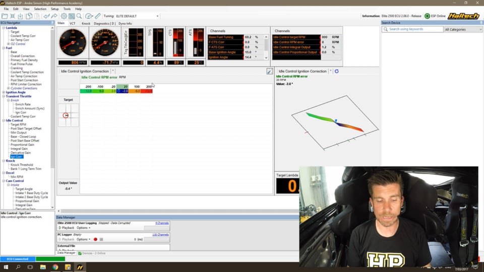
| 23:20 | Now, to give you some tips here on what we can look at to help tune this, I've set up a few channels up here in the top right corner of my screen, and these are some channels related to the idle speed control system, that are important to look at. |
| 23:36 | And particularly here at the top we have our current Idle Control Target RPM, below this we have our error, so this is essentially just how far away our current engine speed is from our target. |
| 23:49 | Now this is an alternative way of tuning our base table here, also displaying our integral and our proportional outputs, so this is important to note, this isn't the integral and proportional gains, these are the integral and proportional outputs so this is what the closed loop system is doing to affect the final throttle opening. |
| 24:14 | So you can see right now while I've been talking, we have an integral gain of minus 6%, and essentially what that means is that the current value at 90 degrees centigrade, where we're operating, is around about 6% too high. |
| 24:30 | So if we simply enter a value of 42, what's going to happen here when I press Enter, is that initially our idle speed is going to drop. |
| 24:39 | Now, this is because currently the integral component is removing 6%, so it's going to drop because we'll still be pulling 6% out, and then you'll watch the integral gain will slowly, the integral output will slowly increase back and we should end up somewhere around about zero so, let's press OK now and see what happens. |
| 25:01 | OK, see our idle speed has dropped, you can see now we've got an error of 25 rpm, or at least it was when I mentioned that, and you can see that while I've been talking as well, our integral output is winding back down towards, or back up towards zero. |
| 25:17 | So, we can choose to tune this in a couple of different ways, but the key point here is to understand the interaction if we have closed loop enabled. |
| 25:28 | So, we could choose to go and zero out our proportional, our integral, and our derivative gain tables, that essentially forces the ECU into open loop, and then we can simply go through and adjust our base table value until we've met our rpm target, that's one way of doing it. |
| 25:46 | The other way of doing it is to leave our closed loop control active, and simply view these channels that we're looking at now, and use the combined output values that the closed loop system is applying, to help guide us in the way we're adjusting our final values in our base table. |
| 26:08 | Really the way you do that is up to you but the important point here, and I think a lot of people overlook, is when they're tuning this table, they don't understand the closed loop interaction, so they've got a value in this table that is what we had before, 48%, the target idle speed is bang on, everything seems like it's happy days, but it's very easy to overlook that the only reason that our target idle speed is being met correctly is because the integral component is actually removing 6%, because our base duty cycle table is set slightly too high. |
| 26:45 | OK, now once we've got our base table completely dialed in and this again, just to reiterate, needs to be done from cold start, and it needs to be done after our fuel and ignition tables have been correctly dialed in, once we've got this table really close so we're as close as we can to our target, at that point we can enable our closed loop control, so we can enable our P, I and D gains, which we'll talk about shortly, and that's also the time where I would be adding in, or turning on our long term trim table, and we've already talked about how we can utilize that. |
| 27:26 | Now there's one other aspect that I wanted to mention here, we've just touched on it briefly, if we go back to our settings, we can see we had a Decel Offset and a Decel Offset Decay Time, and I just wanted to talk about the interaction of those two aspects. |
| 27:41 | And what this does is it helps to catch the engine rpm and prevent stalling, or prevent the rpm dropping excessively, if we give a sharp throttle input and then come back to idle. |
| 27:54 | And that's an area that a lot of ECUs struggle and a lot of tuners struggle, is to really come back down from a high rpm and just clamp straight to our target idle speed, without the idle speed either flaring high, or dropping down excessively low and risking stalling. |
| 28:12 | So what these two parameters do here is, the decel offset increases the duty cycle momentarily, in this case by 6.5%, obviously we can adjust this to suit, and it will hold that or decay that over 1.5 seconds so, what it does is it initially bumps our throttle opening slightly to catch the rpm, and then once the rpm gets close it'll drop that back down and decay it over 1.5 seconds. |
| 28:39 | So, let's just have a quick look at how that works, so, let's for example add quite a large percentage, let's go with 20, and what I want you to do here is watch the engine rpm in our gauge on the top left. |
| 28:55 | I'll just drop the rpm, OK so you can see that we really really slowly came back down to our idle speed, it was excessively slow, we actually started by catching the rpm up at around 1,400 rpm, obviously not what we want, let's go to the other extreme and I'll set this to zero, essentially disabling that function, and I'll do exactly the same again. |
| 29:19 | OK, so this time we dropped down to 650-odd rpm, and then the idle speed control system caught up and pulled it back up to 800. |
| 29:29 | So, if we can correctly tune that decel offset, that's going to give us really good control as our rpm comes back down, and again that's going to help the idle speed control system stability, because often what we find is if the rpm drops below our target, this actually brings in an oscillation in the control algorithm, and we end up with our idle speed sort of dipping up and down above our target set point for a few seconds before it finally settles down. |
| 29:58 | OK, the last part we're going to talk about, oh actually before we move on, we also have a Post Start Base Offset table, and this is a little bit like the Post Start Target Offset table, that we already spoke about, so what this does is it adds additional opening to our drive by wire throttle, based on a time after start. |
| 30:20 | So again what we will often find is that initially we require a little bit more throttle opening to actually get the engine to start up quickly and achieve idle speed quickly, and then over time we can drop that back down. |
| 30:35 | So again we can tune this table here in order to ensure that after a startup, our idle speed is as close to our target as possible, we're going to not want it to be excessive to flare on startup, and we also don't want the engine to idle low and then gradually sort of pick up over time, so we can use this table to help us with that. |
| 30:56 | OK, so moving on to our P, I and D gains, now I'm not going to spend a huge amount of time discussing how the PID control algorithm works, these are the gains that the closed loop control strategy uses to decide how much to affect the drive by wire throttle opening, or the idle speed control system, in response to an error between our target and our measured rpm. |
| 31:25 | If you want a better explanation of PID tuning please check out the other webinar we have in our archive on PID control strategies. |
| 31:34 | PID is a control algorithm that's applied to a wide variety of closed loop control strategies, it's certainly nothing related specifically to idle speed control tuning here so, that webinar will give you a lot more information on PID tuning, and some strategies to employ if you aren't already familiar with what PID is. |
| 31:59 | Now the type of strategy we use with PID tuning here is really going to depend a lot on the speed of the system to change, and, relatively speaking, idle speed control is quite a slow moving system, it's not like, for example, boost control or cam control, where we can get very very large changes very quickly, generally the idle speed control system is quite slow moving, and in a slow moving system like that it is quite common to simply rely on an integral element to our PID tuning, and the integral element is an element that responds to an error, in relation to time. |
| 32:41 | So, essentially what it's going to do is it's going to look at the error between our idle speed and our target, and as that error is still present, it's going to constantly adjust the output in response to that, so let's have a quick look at our Integral Gain here. |
| 32:57 | So we've got a two-dimensional table, and this is quite a nice feature with the way the PID is integrated in the Haltech Elite, is that we can adjust our gain, relative to our error. |
| 33:09 | And what we want to do here typically is have a larger, more aggressive gain as our error is larger, when we're very close to our target we want to reduce that gain. |
| 33:20 | And, again without going too far into the techniques of PID tuning, we find that if we have a large gain, we're going to end up with a quick response to an error, but it also can result in instability in our control system in terms of our idle speed control tuning, this will show up as an oscillation in our idle speed, so our idle speed's constantly going to be hunting up and down, so if you've got that sort of scenario where your idle speed is hunting, it's quite possible that your closed loop gains may be set too high. |
| 33:57 | Like, so we've got this 2D table of, it's pretty typical of what we would normally see, the numbers in around the zero error, quite small relatively speaking, we've got a value in there at the moment of 200, whereas when we've got a larger error out here, we can see that that value's 500. |
| 34:14 | Again, we can use the channels to monitor what our integral output is doing, so we can see how that's actually responding to an error. |
| 34:26 | And, the technique that I generally use with any PID tuning so that we can start to see the range of values that are going to work for our particular system, is to start by making really broad changes so, for example, a really good place to start is simply to double the gains, and, we want to keep doing that until we start seeing the system become unstable and that's that oscillation I was talking about, once we get to the point then we can go through and halve the gains, and this gives us a really quick way of finding the sort of values or range of values that are workable for our particular system. |
| 35:02 | When it comes to any type of PID tuning, there isn't one single set of values that you can go and hope to apply to absolutely every tuning job, it really does need to be tuned based on the system that you're controlling. |
| 35:18 | Now in this case I have actually also incorporated a small amount of Proportional Gain here, and the reason for this is with the drive by wire throttle we do have a system, the drive by wire throttle system can obviously move and respond very quickly, so I have incorporated some Proportional Gain here, again what we can see is I've used quite small values, in this case a value of 50, down around that zero error, and, slightly more aggressive out at either extremity of that table. |
| 35:54 | It's important to also note for anyone who's coming from another ECU platform and is looking at these gain values and thinking, what do these mean? Haltech represent these PID gains in what they term as a raw value, so this isn't something that you would be familiar with seeing, if you've come from the likes of perhaps Motec or maybe Link where the gains would be much, much smaller. |
| 36:23 | OK, so once we've got a closed loop system that is controlling and doing a really good job of keeping our idle speed stable, there's one more aspect that's also available here at the bottom of our idle speed control list, and this is our Ignition Correction. |
| 36:40 | And this is a really nice function to help the closed loop control system, and again, give us much more stable control, and what it does here is it makes adjustments to our ignition timing, to help control the idle speed. |
| 36:57 | Now we find that the ignition timing will get a much faster response typically to changes in idle speed than a slower moving idle speed control circuit, particularly the likes of a stepper motor or a solenoid, so what we're doing is using very very quick changes in our ignition advance to help adjust the engine torque. |
| 37:20 | Now, the way that works, in a nutshell, is that if we advance the timing towards MBT, what's going to happen is that the engine will pick up torque, and naturally this is displayed as an increase in our idle speed. |
| 37:34 | Conversely, if we retard the timing further away from MBT, in this case that's going to result in the torque being reduced, and hence our idle speed drops. |
| 37:45 | So we can see that this particular table here is again set with an axis of error, idle speed error, and what we're doing is simply, as our idle speed drops, so as we come down below our target idle speed we're adding ignition advance, and likewise as we increase our idle speed above our target, we're retarding the timing. |
| 38:10 | Now it's important to note that these values here in our idle control ignition correction table are a correction, that is applied over and above our base ignition table values. |
| 38:24 | Now there's two things to keep in mind here that are important. |
| 38:27 | Firstly, if you want to make use of idle ignition control, it's really important that you have your normal idle ignition timing, your normal ignition timing in the idle areas, set somewhere below MBT. |
| 38:45 | Now the reason for this is, we need to be able to take advantage of both advancing and retarding the timing, in order to increase and decrease torque. |
| 38:53 | If our natural idle ignition timing is already sitting at or very close to MBT timing, this doesn't really give us any potential to advance the timing and get that increase in torque, so if we want to do this, it's pretty typical to have our base ignition timing at idle sitting somewhere in the region of perhaps 12 to 15 or 16 degrees, somewhere in that range, generally that's going to let us advance. |
| 39:17 | We may find, depending on the engine, that we see increases in idle speed up to perhaps 24 or even 26 degrees, and generally I don't personally like to retard the timing consistently much back below sort of about TDC, zero degrees advance at idle, and if we've got everything working correctly, that should be an adequate range. |
| 39:39 | And, while I'm talking here, we can see if we monitor the actual ignition angle, hopefully it's not too small for you to be able to see, we can see that that is moving around somewhere between about 14 and about 16 degrees while I'm talking, and that is the idle ignition control system in action. |
| 39:57 | Now if we just go back to our ignition base table as well, you can see that the timing that I have in that idle area is very consistent, it's all sitting at 15 degrees, and it's another consideration. |
| 40:11 | If you're interpolating between two cells and your actual main table values for ignition timing are fluctuating quite dramatically based on that, this is also going to upset the ability of your idle speed control system to work, and in fact, will also influence your ability to tune and achieve good idle speed control in the first place so, it's quite important, in my opinion, to make sure that you have solid and stable ignition timing in the idle areas, otherwise you're going to be trying to tune around the varying ignition timing with your base table values. |
| 40:48 | OK so, we're going to move into some questions and answers very shortly, so if you do have anything that you would like me to discuss or explain in more detail, please ask those in the chat box now, and I'll get through to those shortly. |
| 41:03 | I just wanted to go over, now that we've looked at the available configuration, all the settings and all the tables and we now understand what they mean, and have hopefully a better idea of the interaction of those and a good way of tuning each of them, we're gonna go through a strategy that you can actually apply in your own tuning. |
| 41:23 | So, this isn't set in stone, but this is going to make sure that you have a solid and sensible way of approaching your idle speed control tuning, it's gonna make sure that you get good results and don't overlook anything. |
| 41:36 | So what we want to do is start obviously by setting up our base parameters for our control, we want to make sure that physically our control system is set up and working, set up and functional, in particular for our drive by wire throttle system, we want to set our max opening, and remember that max opening we had set to 10%, that represents what is 100% in our base duty cycle table. |
| 42:03 | Once we've done that, we've got everything working, we want to set our system either to open loop, or if you're comfortable leaving it in closed loop, we want to be able to monitor the feedback of our PID control, and see what that's actually doing, how that's influencing the final duty cycle that's being sent out to our drive by wire throttle. |
| 42:25 | We also want to, at this point, set our long term trim table, our long term trim to disabled. |
| 42:31 | We also want to set our target rpm table so that we actually have sensible values, what we would actually like to be achieving. |
| 42:40 | Then once we've got that done we can finally start our engine and we're going to go through there and adjust the base duty cycle table at each of the coolant temperature breakpoints, and there ideally what we want to do is simply start from cold, start the engine and allow it to warm up, and each time we're central in one of those breakpoints we can make any adjustments that we require, based on either the error from our target idle speed, or if we do have closed loop still enabled, we can look at the magnitude of the adjustments that a closed loop system is making. |
| 43:19 | So once we've done that, then we can enable our closed loop, and in most instances with idle speed control I would begin just with the integral components, and the base settings from the Elite default map is actually a pretty good starting place, from my experience so far. |
| 43:37 | Now remember, if you want more instruction on PID tuning, please check out the other webinar that we have in the archive on that, but my initial approach there is to simply start by doubling, or halving those gains, so that we can quickly see the kind of area for those gains that works well. |
| 43:57 | Then we can enable our long term trims, and then we also want to test our decel offset, and finally, we can set up and test our start offsets as well. |
| 44:10 | So if you've gone through all of that in the correct approach, what you're going to end up with hopefully is a closed loop control system, which is dialed in really really accurately, where the actual closed loop feedback has little work to do, and as I've said a couple of times already, that's going to give us the best possible results, that's going to give us the most stable control system. |
| 44:32 | And remember with the benefit of the long term trims, we do have the ability to then send the car out into the real world, drive around in it for a week or so, and then have a look at that long term trim table and see what actual changes the ECU has seen that it's needing to make with the short term, the closed loop feedback, and then we can apply those changes into our base duty cycle table. |
| 44:57 | Alright, let's move onto our questions, we'll see what we've got in here. |
| 45:01 | We've got one from Chad, Motorsport Wiring, when upgrading to a large throttle body, drive by wire throttle body like an LS2 on a 1JZ with an Elite, would it just be a case of adjusting these tables after tuning? Yeah, one of the aspects there that's important to understand is if you're changing to a dramatically different sized drive by wire throttle body, then that's going to quite likely have a large impact on what that max opening setting for the drive by wire throttle is going to need to be. |
| 45:35 | Obviously with a larger throttle body, for the same percentage opening you're actually going to get more air flow, which is obviously going to result in the idle speed being too high, so that's probably one of the first places to start. |
| 45:49 | Generally, not that I've done a lot where I could say that I've just made the sole change of a drive by wire throttle body size, but generally you're going to need to use the maximum opening to kind of rescale your duty cycle table, and then once you've done that, then you're going to still need to go back through and actually optimize that duty cycle table again, it's probably going to be quite close, just by changing that maximum value. |
| 46:21 | Mitch Detailed has asked, if you change your idle max TPS opening, do you have to manually rescale the table it affects? If you changed your maximum throttle opening, what that will do is mean that that entire table, the base duty cycle table, will actually give you more throttle opening. |
| 46:40 | So remember, the numbers in that base duty cycle table are simply a percentage of that max opening, so if you go from, let's say 10 to 20% in that maximum opening, then you've essentially doubled the opening, based on whatever's in your base duty cycle table, so yes you're going to need to go through and rescale that table as well. |
| 47:05 | Racepacks asked, battery offset at idle with electrical load. |
| 47:09 | OK, I'm not quite sure what you're referencing there, if you're talking about injector dead time there, or, whether you're actually talking about an auxiliary table that we can incorporate in order to make changes to our base duty cycle table, so hopefully we'll be able to get a little bit of clarification on what you wanted there. |
| 47:33 | I will mention that there are a range of generic offset tables that you can incorporate through the main settings page, if you see the need, and you can include those for any corrections that you feel need to be made, based on certain operating conditions. |
| 47:51 | And again what these tables allow you to do is essentially remove some of the variation that's natural in the system, and achieve a more stable idle speed control, a good example of this might be if you had an idle up table for when the power steering was active or something of that nature, you could probably also incorporate something similar for an automatic transmission, when you were pulling it into a gear from neutral or park, obviously that results in more load being applied to the engine, and hence the idle speed would drop. |
| 48:26 | Alright, looks like that's the end of our questions so I'll leave it at that for this week. |
| 48:31 | Thank you all for joining us, of course as normal if you do have any further questions that I haven't answered here, please ask those in the forum, and I'll be happy to answer them there. |
| 48:42 | If you haven't already, please jump on our Facebook page and leave us a review, these are really helpful to us, when people are considering using High Performance Academy, these reviews give them the confidence to deal with High Performance Academy, and let's you share your experiences if you're finding High Performance Academy a useful resource, and you like what we're doing, please let the world know, by heading to our Facebook page and leave us a review, we'd love it if it was a five star review too. |
| 49:13 | Alright guys, thanks a lot, we'll see you all next week. |


