Sale ends todayGet 30% off any course (excluding packages)
Ends in --- --- ---
Hi Guys,
I'm looking for some information in regards to wiring my AEM X Series wideband to my Link G4X. I have a number of questions I'm hoping you'll be able to support in answering, while my hands on wiring skills I am very confident in (Crimping, Soldering etc) my technical knowledge on some of the processes is lacking as it's been 10 years since I did my Motorsport Electronics module at University and haven't needed those skills in my automotive career since.
In Summary;
1. How are resistors wired in, in parallel - I.e The physical side of exactly how to wire in a resistor, where in the wire, how is it joined? A wiring diagram is not helping me understand how it should look in the real world.
2. The Link G4X has terminating resistors in the ECU, but the AEM CAN wiring calls for 120ohm Resistors in parrallel at the end of the BUS. So exactly where do the resistors need to so?
Currently the wiring goes
Bosch 02 sensor > Connector > Harness to Gauge > Gauge Power Harness > CAN F Connector > CAN PCB Harness > Link G4X
In this chain above, where do I need to wire in the resistors?
Any help would be great
Kind regards,
Harry
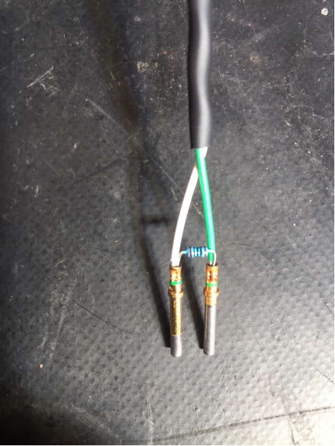
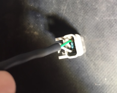
A 120ohm resistor shorting across the CAN H/L wires somewhere close to the AEM connection. For a road car I normally just crimp the legs of the resistor directly into the DTM sockets along with the wires, then RTV into the connector housing for strain relief instead of the original silicon seal.
Hi Adam,
Thanks for the feedback, I've tried to draw out an idiots guide, could you confirm if the assumption below is correct?
Cheers chap!
Yes something like you have drawn will do. It can be on either side of the DTM - AEM or Link side is fine.
A couple of pics attached, this is from a two pin DTM but you get the idea. Practice on a spare terminal first as the lengths of the resistor legs take a bit of trial and error on the first go.


Great, thanks for confirming that i’m on the right page Adam, picture speaks a thousand words for my little brain!
Cheers for the support!
Hi Adam;
Just purchased the link CanLam kit for a Link G4X fitted an 06 Sti,
wired in the 12v+ and GND along with the Can H / Can L wires, Also bought the Cable for the PCB connection for Can 2/OBD and the cable that connects this and the DTM plug, (installed the O2 sensor also)
When going through the the PC Link software to Can setup, I follow the Link instructions and use Can 2 for the module, Select user defined in the mode section, 1 Mbit/s automatically populates. Use Channel one I continue to follow the rest of the setup guide etc.
When it comes to Find devices nothing appears. I find that the software doesn't save any settings.
From the PCB I'm getting 12+ve and GND, I'm getting 1.9+ve and 3.2+ve on the can wires. so the connection from the PCB to the Can plug appears to be ok. Would this issue be related to the lack of resistor? Or something else.
Regards
Stephen
The bus should always be terminated with a resistor, but that doesn't normally prevent it from being found. Are you on recent firmware? - the "find devices" tool wasn't implemented in early firmware, I think it was added around 6.18. But in the old firmware the lambda still worked - just you couldnt assign more than one without the find devices tool.
Can you attach your tune. May have to put in it a zip folder.
Hi Adam;
I'll get the tune file to you shortly, I was going to update the Firmware via the PC link, read some of the warnings around the update and din't complete the update. I've attached a photo of the PCB we've received. (TOP PCB V3.1) (Bottom PCB V 1.8)
