Sale ends todayGet 30% off any course (excluding packages)
Ends in --- --- ---
Hi all,
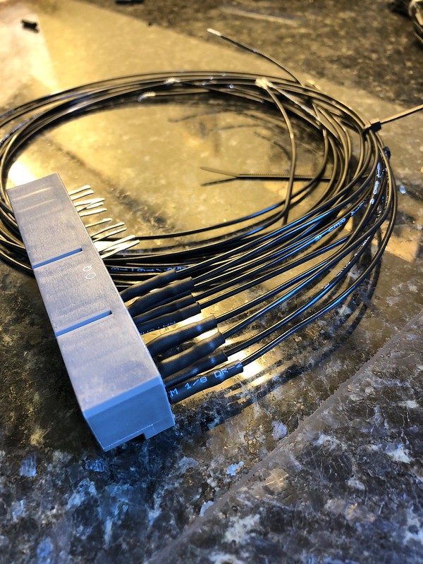
Just looking for some insight into how you all are potting your ECU patch harnesses? I'm building another one currently, and want to 'Pot' where the wires enter (as per below).
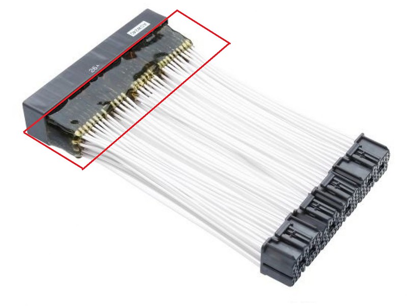
Im interested in how people are making a barrier as such to localise the potted area as per the second pic.
Any help appreciated.
Thanks!
Current harness construction: Tefzel wire, Raychem B-155-150* sleeves, then DR25 on top.

'Localised' potting example.

I've only done this a couple of times with an ECU header before, and I used masking tape. It was not a fantastic way to go to be honest, would also be interested to hear how people have gone about this.
When I've needed to do it with sensors, I've usually machined a boss that presses onto the sensor body, and surrounds the wiring connections, and is then potted.
Thanks Zac,
I'll wait to see if there is any other input. If not ill think of something and report back with the results!
Would a 3d print help? If you think it might, fire me over some dimensions.
Hi Tim,
Thanks for the offer, I suppose a 3D printed 'barrier' that slides over the top to contain the potting could work! I can take some measurements and fire them over.
Im not sure if it would end up being a one use part though as you would probs have to break it off otherwise itll set in with the potting compound too, unless i can line it with something...Worth a try though if you are happy to print something :)
It might be something that's sacrificial, you're right.
See if anyone comes up with a better idea, mine is just a suggestion, and not something I've ever tried myself. If I do end up printing you something I wouldn't feel comfortable charging you for it, so it would be a case of you trying it to see if it works.
I can't seem to find a PM system on here, so feel free to find me on FB.
What type of epoxy is used for potting connectors like this? Hoping it is something cheaper than RT125.
I am reading up to get ready to do something like this in the near future, looking at the pics, wire is soldered to the pin from the ecu socket, heatshrunk then the whole thing potted to provide strain relief and vibration protection?
Are there other ways of tackling it? I have an idea in my head of having a pcb made (as ill be using a pcb style socket from the factory ecu) with a more generic (Superseal etc) style pcb mount socket on the other end, so I would have factory ecu harness-plug>socket-pcb-socket>Superseal crimp plug>short length of wire>Aftermarket ECU crimp plug>ECU.
Is that overdoing it? my reasoning is I wont have any soldered wires and the short wire part leaves some flexibility in messing about with pinout configs and a space to wire in breakouts from either side.
Any links, articles, videos on doing similar very appreciated, as well as any websites I can trawl to see if a crimp version of the ECU socket is available anywhere (the single supplier of a plug and play ecu for my car solders to a factory socket, another ecu manufacturer looking to make one says available but expensive, and wont tell where)
You must be confident the wiring is permanent.
What I would probably do, in your position, is get some stiff cardboard and cover one side of it with insulation or duct tape, spray some non-stick/parting media/silicone lubricant on it. Then cut or fold it to size and tape that to the component being potted. If you are carefull and have the height the same all round, you can pour in the media you want to pot with* and allow to set before removing the card.
*there are many available or you can use some RTV and a caulking gun - a fine tip should allow you to get right to the bottom to ensure good coverage - I haven't used it on electronics, but a similar method works well for filling the void space in engine and transmission mounts to stiffen them but still allow some vibration dampening.
What type of epoxy is used for potting connectors like this? Hoping it is something cheaper than RT125.
any one answer this question yet as im curious too?
