095 | Selecting a Trigger System
Summary
The trigger system fitted to your engine provides the most critical information the ECU needs in order to accurately measure engine speed and engine position. Since all of the ECUs calculations are made off this data, it’s essential to make sure it’s reliable and accurate. In this webinar we will discuss some of the popular options available when selecting an aftermarket trigger system, and what you need to know to select and configure a suitable option for your engine.
| 00:00 | - Hi guys, thanks for joining us for this webinar and in this webinar we're going to be investigating trigger systems on ECUs. |
| 00:08 | And this is one of the most critical inputs, if not the most critical input that any ECU needs in order to be able to do its job properly. |
| 00:18 | So when I use the term trigger systems, what I'm talking about is the input information that tells the ECU how fast the engine is turning, so what the engine RPM or engine speed is as well as in most current engines we're also going to be looking at engine position and by engine position I'm talking about which cylinder is firing at any particular point in time. |
| 00:45 | Now there's a really important distinction here that's really easy to overlook and that's for a four stroke engine, we need to complete two full revolutions of the engine, so that's 720 degrees of crankshaft rotation to complete one engine cycle. |
| 01:03 | This is important because what it means is the ECU can't get all of the required information directly from the crankshaft itself, what we need is an input that's operating at half of the engine speed in order to let the ECU know whether it's on the exhaust stroke or on the compression stroke for example. |
| 01:28 | So we're going to look at how the ECU can get all of that information and what the various ways of getting that information into the ECU are. |
| 01:37 | And really when it comes down to it, there's about as many different trigger systems available on modern engines as there are engines out there. |
| 01:46 | Kind of every engine manufacturer thinks that they've got their own unique approach that's going to give them an advantage in terms of getting the best and correct information through to the ECU. |
| 01:59 | So there really is no single fixed trigger system that we need to be able to decode and apply to every engine. |
| 02:08 | And that's why one of the jobs when we're setting up an ECU for a new engine is to input the trigger information so that it knows, the ECU knows how to correctly decode the information from the inputs. |
| 02:22 | Now those trigger inputs, I'm calling them here trigger inputs but they will have different names depending on the ECU that you're wiring or working in. |
| 02:33 | So for example, you might be used to referring to them as trig one and trig two, also commonly referred to as ref or reference and sync, or synchronisation. |
| 02:45 | There's a variety of different techniques of referring to these but essentially it's all that information that's telling us about the engine speed and engine position. |
| 02:56 | So they are so critical because all of the calculations that the ECU makes based on fuel and ignition timing are based on the accuracy of this information. |
| 03:07 | So if the ECU doesn't accurately know engine speed and position, it's kind of blind and these calculations can't be performed correctly. |
| 03:16 | And from our perspective what this means is that the amount of fuel or ignition timing that we get could be dramatically different to what we're actually expecting. |
| 03:27 | Now I'll point out that this webinar will also run in conjunction or fairly closely with our next webinar which will be diagnosing triggering errors so if you've watched this webinar in the archive, make sure that you check out the next one along as well, all of the information will be relevant and that will build on what we're talking about in this webinar. |
| 03:50 | Let's start by having a quick look at an example of what it looks like when we get it wrong, when the triggering information isn't sound. |
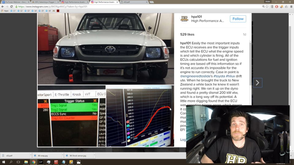
| 03:58 | So if we can just go to my laptop screen, and this is actually a post I put up on Instagram yesterday. |
| 04:05 | This is a Toyota Hilux drift ute built by Nigel at Engineered to Slide over in Melbourne and we were involved in the wiring of that back in Australia. |
| 04:16 | And we tuned it on a rolling road dyno in Australia, everything went perfectly. |
| 04:20 | Nigel brought the car to New Zealand, he'd already done some filming with the car and he knew it wasn't quite sounding right, wasn't quite feeling right so when we got the car back to our workshop in Wellington, I ran it up on our Dynapack dyno and I'll just try and trace over the line roughly. |
| 04:37 | We ended up with something around about 195 kW at the wheels. |
| 04:44 | Pretty uninspiring and a long way shy of where it should have been. |
| 04:49 | And in particular, hopefully you can see this on your screens. |
| 04:52 | We can see that in the mid part of the run there is a lot of erratic, a very erratic shape to the power curve. |
| 05:01 | So it's jumping up and down, it's definitely far from smooth. |
| 05:05 | Now at the time, normally if you've got a triggering error or the engine's clearly audibly misfiring, you're going to hear this, you're going to really notice it and it's really hard to miss, particularly for a tuner that's reasonably experienced, you tend to build up a bit of an ear for when an engine isn't quite running smoothly and correctly. |
| 05:26 | And in this case, while it didn't quite sound right, it also has basically an open exhaust and he also has a really unique exhaust manifold which has one very long runner and that tends to create quite a unique sound in the exhaust system anyway. |
| 05:44 | So it wasn't as clear and obvious to diagnose as perhaps maybe it normally would have been. |
| 05:50 | However I knew the power was nowhere near what I was expecting. |
| 05:54 | And by looking at the trigger diagnostics inside the Link ECU, we have the trig one error counter. |
| 06:04 | Which in Link G4 + or Vi-PEC speak, this is probably one of the key aspects, key parameters to keep your eye on. |
| 06:11 | If you're getting triggering errors, this counter will increment. |
| 06:15 | And we could see that after a couple of runs on the dyno, this is sitting at 222. |
| 06:21 | It's not uncommon to see this increment by one or two when we first start the engine until the engine actually gets synchronised correctly but certainly under normal operating conditions we shouldn't see any further incrementation of that value. |
| 06:35 | So as soon as I see that, I know that that's a problem. |
| 06:39 | We did some further diagnosis and looked at a scope capture of the trigger inputs and found that the sync tooth which was fitted to one of the camshafts had moved slightly between when I tuned it in Australia and it coming to New Zealand. |
| 06:55 | We just simply corrected that, it was all of about a two minute job in the end and we can see that the yellow trace that we ended up with was a little bit more representative of what we're expecting, 320 kW at the wheels. |
| 07:09 | The other aspect with that trace which is just as important is the overall values. |
| 07:14 | You can see how much smoother that particular trace is, it's not showing that erratic nature through the mid range. |
| 07:22 | So this is the sort of problem we're likely to see, or one of the sorts of problems we're likely to see if we haven't got good triggering through to the ECU and the ECU's getting confused with the engine RPM or the engine position. |
| 07:38 | Now in this case, looking at what was happening we were ending up with an erratic lambda trace, the fuelling wasn't correct and also the ignition timing was massively retarded over what we were actually trying to ask for. |
| 07:53 | So massively retarded over the values in the actual igniiton table. |
| 07:57 | Fixed all of those problems up and of course that's where we get the correct result which we were expecting. |
| 08:06 | OK so now we've sort of seen what it looks like when we've got it wrong, let's talk about the requirements a little bit further. |
| 08:15 | Now I've talked about the engine speed input and it is quite possible to run an ECU where it's only getting input from the, either the crankshaft or from a camshaft and it's simply telling the ECU what the engine speed is. |
| 08:31 | However, if we want to run a sequential injection system, we want to run direct fire coil on plug ignition, then we also need the ECU to know what position in the engine cycle it's on and that's where we need that synchronisation pulse as well. |
| 08:52 | So just to reiterate, the synchronisation pulse, we need one input every 720 degrees of engine rotation and because the cam train, the camshafts spin at half engine speed, it's obviously a sensible place to locate that synchronisation pulse. |
| 09:09 | Either directly off a camshaft or if you've got an engine that runs a distributor, the distributor also runs at half engine speed so that's another place that we can get that synchronisation pulse. |
| 09:23 | Now let's talk about the location of those sensors, I've just said that in order to get a synchronisation pulse, we need to have at least one of the sensors, the sync pulse, coming from a camshaft or something turning at half engine speed, we simply can't get that information straight from the crankshaft. |
| 09:42 | We can also get our engine speed straight from the camshaft as well, even though the cams are turning at half engine speed, obviously as long as we've got that input, we know it's on the camshaft, we can multiply it by two and that's going to give us the engine speed. |
| 09:58 | On that basis it wouldn't be a stretch to think that the camshaft or a distributor is possibly the ideal place to get all of our triggering information from. |
| 10:09 | And unfortunately that's not the case. |
| 10:12 | This is actually a situation that many factory OE engines use, case in point would be Nissan SR20 DET uses a sensor driven off a camshaft for both ref and sync or trig one and trig two. |
| 10:31 | Mitsubishi 4G63, or at least the earlier ones also used a cam angle sensor driven off a camshaft to deduce all of their information. |
| 10:41 | Now the problem with this, or where we can get issues with this is it's not unusual, particularly when we start modifying the engine, perhaps we fit a set of more aggressive camshafts, perhaps those are also matched with a more aggressive or stronger valve spring, it's not uncommon to get resonant frequencies occurring in the cam train which will then be transferred through to our cam angle sensor and in essence what we end up with, this is a sensor I'm going to show you again a little bit later on, this is a Nissan SR20 DET sensor. |
| 11:16 | So under normal situation, we're driving this off the camshaft and it's turning smoothly. |
| 11:22 | And really to exaggerate things, when we get to a point of resonance, what's happening is the sensor is moving backwards and forwards really rapidly at a fixed RPM. |
| 11:30 | And that's giving the ECU some inaccurate data about the engine RPM and position. |
| 11:36 | So taking all of our data from the camshaft is not really what we want to be doing in the perfect world. |
| 11:45 | In the perfect world what we want, obviously our synchronisation pulse needs to come from the camshaft as we've discussed but we really want to fit our engine speed sensor and our reference sensor directly to the crankshaft, either at the front or at the back, maybe perhaps even somewhere along the crankshaft and that's then directly taking the engine speed from the crankshaft and that's the reference we want. |
| 12:10 | When we're timing things such as injection angle or much more importantly, our ignition timing, we're always referencing top dead centre based on the crankshaft location so obviously it makes sense to locate our sensor directly on the crankshaft. |
| 12:27 | OK so now we've talked about our sensor location. |
| 12:31 | Let's talk about what we actually want or what we need to give the ECU. |
| 12:37 | So in the perfect world, what we really want it to give the ECU a high tooth count. |
| 12:42 | So what I mean by this is we want a high number of teeth or inputs to the ECU per crankshaft revolution. |
| 12:51 | And this is going to give the ECU a lot of data about the crankshaft position. |
| 12:57 | So in other words, the crankshaft doesn't need to rotate very far until the ECU gets another input, another tooth input to tell it what's going on. |
| 13:06 | So if we've got a lot of teeth on the crankshaft trigger wheel, this is going to give the ECU a lot of data and the ECU's going to be able to do a really good job of telling exactly what the engine speed is and whether it's accelerating or decelerating between one tooth and the next. |
| 13:26 | Now how that looks, what difference this makes, if we've got a high tooth count, particularly at low engine speeds such as idle, if we've got a timing light on the ignition one coil and let's say we've fixed our timing at 10 degrees, and we've got the engine sitting there idling, with a high tooth count, because the ECU's getting updated very very frequently on engine speed, this allows the ECU to very accurately control our ignition timing. |
| 13:58 | So with a high tooth count, if we've got our timing light and we're pointing down on the crank pulley and we're looking at our ignition timing, we're going to see an incredibly stable ignition timing, it's not going to be moving around at all. |
| 14:12 | If we take that to the flipside though, we look at a very low tooth count, let's say we only have four teeth on our crankshaft and that's four teeth per revolution so the ECU's now only getting four updates per crankshaft revolution about the engine speed and position. |
| 14:30 | This time, when we're at idle at low RPM because the input, the information coming through to the ECU is a little bit more sporadic, it's quite possible that between the ECU getting one tooth through to it and the next tooth through to it, that's going to be 90 degrees later, it's quite possible that the engine speed may have actually sped up or slowed down slightly. |
| 14:52 | And until that next tooth comes through, the ECU won't know what's happened so it's working, it's calculating based on the engine speed remaining consistent. |
| 15:00 | Now particularly if you've got a big cam, an aggressive idle where the engine is loping quite a lot, we're going to see the engine RPM physically moving up and down at idle quite dramatically. |
| 15:12 | So if we've got a very low tooth count at idle in particular, and again we're looking at our ignition timing with the timing light, we're probably going to see our ignition timing also move up and down a little bit. |
| 15:25 | Now it's not going to be particularly dramatic, we might see our ignition timing fluctuate around maybe three or four degrees at idle as the engine lopes forwards and backwards or up and down in its engine speed. |
| 15:39 | Now the thing is, we're talking here only about idle, we're talking about very low engine speed and frankly while it's nice to have a rock stable ignition timing regardless of our engine RPM, the reality is at such low idle speed, it's really not that critical. |
| 15:58 | And as soon as we blip the throttle, we bring the RPM up to say 2000 or 3000 RPM, even with our very low tooth count of perhaps four teeth, we're now getting much more information coming through to the ECU much quicker and also at 3000 RPM the engine doesn't physically have the opportunity to change engine speed dramatically before it's turned through the next 90 degrees. |
| 16:22 | So what I'm getting at here is even with what is a relatively low tooth count, as soon as we're up above idle, we're actually still getting a lot of information through to the ECU and that allows the ECU to still do a really good job of controlling idle speed. |
| 16:38 | The other problem as well is if we have a very high tooth count, this gives more opportunity for the ECU to become confused and we're going to be talking about tooth count quite a lot in this webinar because it's probably one of the most important parts. |
| 16:57 | Now I'm just going to talk here about the Nissan SR20 DET so this is an optical sensor, hopefully you can see this, this probably is familiar to most people who have been tuning for some time because it is a really problematic type of trigger input. |
| 17:15 | And it's a disc which has, on the outside, 360 very very small slots. |
| 17:21 | Now remember this is also being driven by the camshaft so at half engine speed so we're seeing 180 inputs or teeth through to the ECU per engine revolution. |
| 17:33 | So on the face of it, this would seem to be ideal, we've got a very high tooth count, remember this is going to give us that high resolution. |
| 17:41 | The problem is at higher speed, the ECU is simply getting so much information through from that trigger input that it's very easy for it to become confused, then on top of that we also have the problem that we've talked about with resonant frequencies or harmonics occurring in the cam train and essentially jiggling this sensor backwards and forwards and it doesn't take very much movement for the sensor to read the same tooth multiple times, that's where we start seeing the RPM really get upset. |
| 18:15 | So very high tooth counts can actually be quite problematic and as I've said, we're going to talk a little bit more about tooth counts and perhaps what I might like to consider is an ideal scenario a little bit further on. |
| 18:31 | Actually we'll talk about that right now, not too much further on at all. |
| 18:35 | We'll talk about some of the practical options that are common in terms of trigger systems that we might like to use in the aftermarket. |
| 18:44 | So we'll start with the most common would be a multi tooth wheel or trigger disc that's fitted to the crankshaft. |
| 18:54 | Something like this for example. |
| 18:57 | So in this case we have a 12 tooth wheel. |
| 19:00 | The number of teeth isn't essential but this is a trigger wheel that we can modify and fit to our crankshaft and then we can use a sensor to pick up from that particular wheel. |
| 19:11 | We've got a slightly different variation on exactly the same theme here with one that's suitable to fit a late model Mitsubishi 4G63 engine. |
| 19:21 | So on top of that we're also going to have a single pulse or a synchronisation pulse coming from our cam train which is going to define the synchronisation position or which engine cycle we're on. |
| 19:36 | So this is one of the most common ways of doing this and when we're using a multi tooth with a single sync pulse, we obviously have the ability to define how many teeth we want. |
| 19:48 | We've talked a little bit in my previous example about four teeth and this is probably a lower tooth count than we would typically go for. |
| 19:56 | My own personal favourite, I'm very fond of using a 12 tooth wheel on our crankshaft. |
| 20:03 | That's going to still give enough input data that we're going to get really stable ignition timing, stable information through to the ECU at idle speed. |
| 20:14 | The flipside of that, I've run the 12 tooth trigger disc up to perhaps 11,000 RPM in drag applications and at high RPM we're not overdoing the input information to the ECU, we don't have a huge number of teeth per revolution so the ECU can still cope quite happily with that. |
| 20:41 | Probably the more important aspect though when we're using a multi tooth trigger disc with a single sync is in order for the ECU to be able to do its job properly and decide which engine cycle we're on, it's really important that the synchronisation tooth, remember this is going to be coming from our camshaft or from something that's been driven by the cam, it's really important that that occurs exactly halfway between two of these crank teeth. |
| 21:13 | Now the reason it's important for it to occur in between is this gives a big window for the cam belts to stretch or maybe the cam chain to move slightly and it's still going to occur in the middle. |
| 21:29 | What we get is a real big problem, this is probably the most common issue if we're using a multi tooth trigger on the crank with a single tooth off a camshaft, if the sensor moves around and all of a sudden our synchronisation pulse is occurring at or really really close to one of the reference teeth off the crankshaft, it doesn't take much for everything to move just minutely, all of a sudden it flips over to the other side of a reference tooth due to again, cam belt stretch or some movement in the cam chain and then the ECU is expecting to see 12 reference teeth and then a synchronisation tooth. |
| 22:10 | Now all of a sudden it's either seeing 11 teeth and a synchronisation tooth that it wasn't expecting to see or it's been counting through, it's got to 12, it's waiting to see the synchronisation tooth but instead it's seeing an extra reference tooth before getting to the synchronisation tooth. |
| 22:27 | So this is a really big problem for the ECU and essentially it throws its hands up in the air and it says I don't know what to do and it just shuts down until everything comes back into synchronisation and this is going to cause a momentary misfire, it's going to lose count, it's going to lose position and we're not going to be able to get correct fuelling or ignition timing. |
| 22:48 | So that's the key point is ensuring that our synchronisation tooth is occurring in between two of our reference teeth. |
| 22:58 | Now when we go to the likes of a 24 tooth wheel on the crankshaft, which is another common input, this is still workable, it's still effective but obviously with double the teeth on our crank wheel, we've now halved the size of this window and it makes it a little bit harder for us to achieve proper synchronisation or it makes it more likely that that sync tooth is going to pop across to the other side of one of the reference teeth. |
| 23:28 | So 24 teeth is workable however we do need to be much more careful with our location of our synchronisation tooth. |
| 23:38 | Now when I'm talking about that sync tooth location, I'm going to give you a practical example of this, it might seem logical as I've kind of just mentioned that we want the tooth to occur exactly halfway in between. |
| 23:51 | Now in some instances that might not quite be accurate though and that might not be quite the case so let's jump back into my logging and I'll show you a really horrible log file of an engine demonstrating some massive problems with synchronisation or trigger inputs in general. |
| 24:11 | So I'll just talk through what we've got here, this is on a drag engine, we've got our engine RPM up the top, we've got our throttle position down below. |
| 24:19 | This is actually at a drag strip on a full power run. |
| 24:23 | We've got our manifold pressure and then another parameter that I'm logging, And this is a parameter that MoTeC use and it's called sync relative position. |
| 24:32 | So essentially what this is saying is where abouts the sync tooth is occurring relative to the reference teeth. |
| 24:40 | And in this case if we had a value of 50%, what that would mean is that the sync tooth was occurring exactly halfway between two of the reference teeth. |
| 24:50 | Now we've got values up here if you can't see of 100 and down here of zero. |
| 24:56 | Now what we can see is it's quite a messy signal. |
| 24:58 | There's a huge amount of data here in the middle which is where we were having problems, we actually had the ECU cutting out because it was having triggering errors. |
| 25:08 | But what we can see is we've actually got a trend, if we look through here anyway, we can see that our synchronisation position, our relative position is actually always moving. |
| 25:20 | And this might seem unlikely to some people without seeing data like this. |
| 25:25 | And one of the reasons we see this is because particularly if we're using a cam belt, that cam belt will stretch as the engine RPM increases. |
| 25:35 | So what we tend to see, because the synchronisation tooth is driven off the camshaft, as the camshaft stretches we're actually seeing the synchronisation tooth retard slightly with relation to the crank trigger wheel. |
| 25:52 | So in a worse case scenario and this is kind of what we had going on here. |
| 25:57 | In a worse case scenario, what we can find is we start with the sync tooth exactly at 50% at idle. |
| 26:04 | Ideally where we think that might want to be. |
| 26:07 | But as the RPM increases, particularly as we get up to perhaps 10,000 or 11,000 RPM, what we find is the relative, the sync relative position actually starts to drift away because the synchronisation position is moving relative to the two reference teeth and if we get enough cam belt stretch it can be possible for that to jump across to the other side of a reference tooth and create that triggering error that we've talked about. |
| 26:33 | So in this case, if we're getting a lot of cam belt stretch and we're monitoring this, it can be beneficial to actually offset the synchronisation tooth slightly to give us a bigger window, in other words to allow the synchronisation position to move and not get anywhere near crossing over one of those reference teeth. |
| 26:53 | Alright just thought a little bit of a demonstration of that might be useful. |
| 26:59 | And also just while we're on that note, this is some data that I used to log on my own drag car, another 4G63 12 tooth trigger wheel on the crank, single tooth off the camshaft and we started running that engine with a factory Mitsubishi cam belt and then at one point we went to one of the aftermarket gates or HKS or GReddy style stronger racing cam belts and up until that point I never really knew if those cam belts were actually all hype or whether they were in fact stronger. |
| 27:33 | What we found from our data logging is because we could essentially look at the sync position and measure the cam belt stretch, I could actually see that the racing cam belt did in fact stretch a little bit less than the factory cam belt. |
| 27:48 | So there's a useless little piece of information to add that's relevant to this. |
| 27:56 | OK so we've talked about the multi tooth crank trigger with a single synchronisation pulse. |
| 28:04 | Now in my experience, this is probably still the most common aftermarket triggering method that you're likely to come across and when set up correctly, it does work exceptionally well. |
| 28:15 | The other option that we can do, can use, and this is really common in a lot of OE applications, is what's called a multi tooth missing trigger wheel. |
| 28:26 | Now as its name implies, this is a multi tooth wheel that has generally one or two missing teeth so while I don't have one here to show you, if we go back to our 12 tooth, we're not going to generally use such a low tooth count for a missing wheel, more common would be the two common ones are 36 minus two and 60 minus two, both very common in European cars. |
| 28:50 | So in this case let's say we were talking about a missing tooth wheel and it was a 12 minus two, we'd have 12 evenly spaced teeth as we do on this wheel, and then we'd simply lop two of them off. |
| 29:02 | And what it does is it creates a gap which is the missing teeth. |
| 29:07 | So as I said, we're not going to do that with a 12 tooth wheel, the tooth count isn't high enough, 36 minus two or 60 minus two would be the common ways of doing this. |
| 29:17 | Now what this does is it gives us a little bit more information through to the ECU. |
| 29:24 | Now it's getting engine RPM or engine speed information and this 36 or 60 minus two missing tooth wheel would be fitted to the crankshaft. |
| 29:33 | The ECU can also detect the missing teeth, it knows the frequency of the teeth input that it's seeing, so it knows when it's missed out two of the teeth. |
| 29:43 | So when it sees those missing teeth it knows where abouts the engine is in terms of which piston is at TDC so it knows where TDC on number one cylinder is. |
| 29:56 | So gives it a little bit more information because it now knows a little bit more information about where in the engine cycle it is. |
| 30:03 | Of course this still isn't all the information it needs, because the missing tooth wheel is on the crankshaft, we're still seeing that missing tooth twice per engine cycle. |
| 30:14 | So the ECU still doesn't know if it's at TDC on number on on the compression stroke or on the exhaust stroke. |
| 30:22 | In order to get that information we still need a synchronisation tooth. |
| 30:26 | Now the reason I'm going through this process though is the missing tooth wheel does give us one big advantage over the multi tooth single sync pulse. |
| 30:39 | And that's the location of our synchronisation input is no longer so critical. |
| 30:44 | Essentially we can now locate our synchronisation pulse just about anywhere in the engine cycle we like, provided it doesn't occur anywhere near that gap. |
| 30:56 | So that gives us a much wider range of our engine cycle. |
| 31:01 | So now instead of trying to locate our synchronisation tooth in a very tiny little gap, instead we can locate it around basically most of the engine's cycle and it's not going to be a problem. |
| 31:16 | So this gives us really clean triggering and another option we have here as well is what's known as a multi tooth trigger system with a cam level input. |
| 31:29 | So the cam level, instead of now looking at a synchronisation pulse, just a single pulse that happens once per camshaft revolution, what we have essentially is a trigger input from the camshaft that's high or on for 180 degrees of the camshaft rotation and then it's off or low for the other 180 degrees. |
| 31:52 | And when we combined this with a missing tooth trigger wheel, what it does is it actually allows the ECU to synchronise a little bit quicker because as soon as the engine starts rotating, it's already getting that input from the synchronisation pulse so it knows whether the camshaft level is high or low. |
| 32:10 | And then all it needs to do is wait for the first time it sees that missing tooth in order to correctly synchronise and then start actually providing spark and fuel. |
| 32:21 | So that cam level just gives us the advantage of being able to achieve synchronisation often a little bit quicker. |
| 32:31 | OK so one of the problems with the multi tooth missing though is we do start to get to a situation, particularly at very high engine speeds where we've got a lot of tooth information coming through to the ECU. |
| 32:46 | Particularly if you're using a factory 60 minus two trigger wheel and you're perhaps building an engine that you expect to rev to 8000, 9000 or 10,000 RPM, this presents a huge amount of information to the ECU at these very high RPMs. |
| 33:02 | And some ECUs may struggle a little bit to cope with that amount of information. |
| 33:09 | So this is why my personal preference, while there are some advantages with the missing tooth trigger systems, my personal preference is still along the lines of the multi tooth trigger on the crank with a single synchronisation pulse. |
| 33:26 | OK so now we're going to talk just briefly about the types of sensor that we can use for our triggering systems and really these are broken down into, there's three types of sensor, although two act quite similar. |
| 33:42 | So the first is a reluctor or magnetic style pickup and this is used with a ferrous trigger wheel and it creates a voltage in the sensor as the trigger wheel passes by the sensor so this creates an AC style waveform which we're going to have a look at very shortly. |
| 34:08 | It means that the sensor isn't powered, with a reluctor sensor, a magnetic sensor we're going to typically have a two wire sensor. |
| 34:17 | The other two sensors are a hall sensor or an optical sensor and these are a powered sensor and they create a square wave output. |
| 34:28 | So I've got here what is quite a common sensor for both vehicle speed as well as for trigger inputs. |
| 34:38 | It's known generically as a GT101 hall sensor. |
| 34:42 | Can be used for engine speed but as we'll talk about very shortly, can be quite problematic as well. |
| 34:49 | And then, if I've got one here, we've got an optical, sorry, I'll try this one here, the optical sensor here on the Nissan cam angle sensor which is simply looking at the gap in these teeth on the trigger wheel. |
| 35:08 | So you might find between different manufacturers one will tend to favour an optical sensor, one will tend to favour a hall sensor and others will tend to favour the reluctor or magnetic sensor, there's no correct or no perfect answer to the systems. |
| 35:25 | However what I wanted to talk about now was the problematic GT101 sensor. |
| 35:30 | These are quite common as I've said, for engine speed and position measurement. |
| 35:35 | However you need to be very careful because these don't work particularly well if we've got a pick up with a high tooth count, particularly if we're running the engine at high RPM. |
| 35:50 | So while I've personally used these with great success with a 12 tooth wheel at 10,000 RPM, in that situation the 12 tooth wheel is really the key to why we can get away with this because we don't have very many inputs to the ECU per engine revolution. |
| 36:07 | On the other hand, every ECU's going to be different here with how it responds but if we're looking at a 36 tooth trigger wheel you're probably going to find that much above about 7000 or 8000 RPM, we're going to find problems with that sensor not giving accurate information to the ECU and we're going to run into trigger problems. |
| 36:30 | Now I'll try my best artistic merit here on my laptop if we can just go to that to try and draw what's going on here. |
| 36:37 | So bear with my crude drawings. |
| 36:40 | So we're going to draw a square wave and this is kind of what we expect we're going to get out of our GT101 sensor. |
| 36:49 | Now the reality is it's not quite like that at the best of times. |
| 36:52 | What we find is that the sensor tends to round off the falling edge, I'm not drawing that particularly well, round off the falling edge which is typically what we're also, our ECU is going to be triggering off. |
| 37:08 | Now that's what we might see at relatively low engine RPM. |
| 37:12 | Now if I draw this again at higher engine RPM, what we find is that that rounding becomes much more prominent and instead of seeing a square wave, we're getting this much more rounded signal and what the ECU is looking at is a point somewhere through here, generally somewhere through the middle of this signal which is the point where it's going to trigger. |
| 37:37 | So when we start seeing that rounding of the signal becoming quite pronounced and dramatic, this can affect the triggering point and basically just confuses the ECU. |
| 37:48 | So that's the key point there, Hall sensors, not particularly useful on high tooth count inputs at very high RPM so be very wary of those. |
| 37:58 | Now we're also going to talk about the reluctor sensor because there's a really important consideration with the reluctor sensor so let me again with my crude preschool artwork, let's try and draw what our reluctor sensor is doing as it goes past the tooth. |
| 38:17 | So we see a signal that kind of looks a little bit like this. |
| 38:21 | And bear with my while I sort of add some detail into this drawing. |
| 38:25 | I'll just do a couple of iterations. |
| 38:29 | So what we have here, let's draw an axis over here, and we kind of have a zero plane going through the middle of this drawing. |
| 38:38 | So what we see is as our sensor goes past the tooth we see the voltage, this is voltage here on our vertical axis, and at this point we're positive. |
| 38:48 | And at this point we're negative. |
| 38:50 | So what we see is the voltage begins to rise as the sensor approaches the tooth or the tooth approaches the sensor I should say. |
| 38:58 | As we go past the tooth, the voltage drops vertically back through zero and becomes negative and then as the tooth moves away from the sensor, we see the voltage decay back up towards zero. |
| 39:11 | So that's kind of a crude look at what the signal out of a reluctor sensor looks like. |
| 39:17 | Now one of the key aspects to the reluctor voltage output is we see the amplitude, so if we're talking about the point we're getting up to here. |
| 39:29 | This is going to vary dramatically based on our engine RPM. |
| 39:33 | So while we might only be seeing an amplitude of perhaps two or maybe three volts at idle, it's quite possible to see 20, 30 or more volts at very high RPM so the wave form is dependent very much on our engine speed. |
| 39:48 | And this influences a couple of things. |
| 39:50 | First of all I want to talk about a really important parameter here which is known, or depends on the ECU you're tuning, known as the arming threshold, perhaps the hysteresis. |
| 40:02 | And essentially what this is, it'll be a two dimensional table in your ECU which defines the arming threshold versus engine RPM. |
| 40:11 | So let's talk about what that is. |
| 40:13 | So let's see, we've got our signal here and we're at idle. |
| 40:17 | So let's say that this point here that we're getting to, our high peak amplitude is something like two volts. |
| 40:26 | Let's just draw that in. |
| 40:28 | So what we want to do is make sure that the ECU is also ignoring background noise, there's going to always be a little bit of background noise on this input here and we want to make sure that the ECU is ignoring that background noise and really only looking at the signal. |
| 40:44 | So what we choose is a trigger point or an arming threshold or a hysteresis value that is around about, my rule of thumb is around about a third of our peak amplitude. |
| 40:59 | So in this case, let's say somewhere around about 0.6, 0.7 volts. |
| 41:06 | So we're going to choose that as our arming threshold. |
| 41:11 | So what the ECU does is when we're at this particular RPM, when it sees the voltage first increase above our arming threshold which it's done right here. |
| 41:20 | It goes OK I'm armed now, I'm looking for a trigger input, I'm waiting for a trigger input so it's ignored any voltages down below that. |
| 41:30 | The important point though is the ECU will actually trigger, at this point here, where the voltage drops back down through zero. |
| 41:40 | So this is the point where the ECU actually triggers, so this is the point the ECU considers that the tooth is past the sensor. |
| 41:49 | OK so what we need to do is understand that that hysteresis, our arming threshold, our voltage, will depend on our engine RPM. |
| 41:57 | And let's say for example, at higher RPM, I'll just draw another really crude trace. |
| 42:04 | Let's say we're getting up to 10 volts. |
| 42:08 | Let's just draw our line in there and we've got our voltage now. |
| 42:13 | Obviously we can't really reference our first drawing because I've done them to the same scale but we're getting up to 10 volts here instead of 2 volts. |
| 42:21 | So again at this RPM, whatever this RPM happened to be, we're going to want to increase our arming threshold, we're going to increase our arming threshold, again somewhere around about a third of the peak amplitude so somewhere around about three, 3.5 volts, that's where we'd want to trigger. |
| 42:42 | Now making sure that we keep this arming threshold relevant to the peak voltage is going to make sure that we always have our best chance of ignoring background noise because our background noise has also increased now with our higher engine speed and if we had kept our 0.6, 0.7 volt trigger voltage that we've used at our low RPM, we're now much more likely to see background noise upsetting our trigger input and causing us trouble. |
| 43:15 | OK so that's the aspect of our arming threshold or hysteresis. |
| 43:21 | The other point I just want to mention is our polarity because this is absolutely critical, we must make sure that our reluctor sensor polarity is set up correctly, or alternatively if our ECU has the ability to trigger off a rising or a falling edge on this input, we want to make sure that we've chosen the correct edge. |
| 43:43 | So the reluctor sensor, we can wire it either way. |
| 43:46 | We looked just before at the trigger, this is probably what we would call a conventional way of wiring our sensor. |
| 43:57 | And what we're doing here is we're triggering on this falling edge. |
| 44:01 | So every time we go back through zero. |
| 44:04 | If on the other hand we'd simply wired that same sensor up the other way, we'd get exactly the same shape to our output, only this time it would be inverted. |
| 44:17 | Now it doesn't really seem that important but it's got a really really critical aspect to it that we need to understand. |
| 44:26 | Let's say that we've got our reluctor set up in our ECU, set to trigger on a falling edge. |
| 44:33 | So that would be relatively conventional, we're expecting to see the signal I first drew but this time, let's just try and draw this as well as I can, this time we've wired our sensor up the wrong way. |
| 44:46 | So now what we've got is our reluctor sensor, our reluctor input, looks something like this. |
| 44:54 | OK so, the ECU can still trigger off this, again I apologise for my cruddy drawing. |
| 45:01 | The ECU can still trigger off this. |
| 45:04 | Remember we've got our peak amplitude here so we're going to be looking at around about a third of whatever that is. |
| 45:10 | So this time, although the signal's up the wrong way, the ECU's still waiting to see that positive arming voltage to be exceeded and this time it happens as that voltage jumped back up through zero. |
| 45:22 | So the ECU arms at this point and it waits until the voltage decays back down to zero to trigger. |
| 45:31 | So you can see that our trigger point still happens, our ECU will still trigger and the engine will still run but remember we're really wanting our trigger to occur at this vertical line where we go back through zero. |
| 45:44 | Instead now it's offset and we're occurring somewhere over to the right. |
| 45:49 | Now what's made worse is when our voltage increases from the sensor, the shape of the curve changes a little bit. |
| 45:58 | Let's try and draw this, now what we see is our peak voltage is increased dramatically. |
| 46:03 | We're going to still go back through zero at the same point but now the important point is that the point where we go back through zero, has now moved. |
| 46:14 | I know this is a little bit hard, long winded to get your head around but the important point here is if we are triggering off the wrong edge of our reluctor setup, or our polarity is wired up incorrectly, what we're going to find is that the trigger point that the ECU sees will shift as the RPM increases and hence the voltage amplitude of our signal increases. |
| 46:39 | And how this is going to transpire, if we've got our engine running, and our first job is to set or calibrate our base ignition timing, we can do that at idle, no big deal, we're going to simply be adjusting our calibration point to suit the fact our trigger point is also offset. |
| 46:58 | What's really going to show up though is when we now increase the RPM, so we rev the engine up to let's say 3000 or 4000 RPM, the amplitude of our reluctor signal increases dramatically and because our reluctor signal is increased dramatically, we see our offset, our timing offset shift. |
| 47:19 | So we actually see, if we've got our timing fixed at say 10 degrees and we set our timing correctly at idle, then we increase our engine RPM, what we're going to see is as we rev the engine up we're going to see our timing drift because our polarity is incorrect. |
| 47:35 | Now this is one of the really common problems we see with a reluctor pickup configuration. |
| 47:40 | And it's really easy to make this mistake and even when you think you've got it right, it still pays to check and this is why anyone who's been through our practical dyno or practical road tuning course would know that one of the key points I always reiterate is when we're setting our base timing, we always want to set our base timing at idle or just above idle and then once we're confident that our timing is correct, we want to then increase the RPM, just so we can confirm that we're not getting any drift associated with the polarity of our sensor. |
| 48:17 | OK I'm going to move into questions and answers very shortly so if you do have any questions, and I see I've got some of them coming through, if we do have any questions, please ask them now in the chat box and I'll go through them in a second. |
| 48:35 | So I just want to reiterate, go back over what I've talked about there. |
| 48:39 | So remember the trigger inputs, they're the most critical inputs the ECU gets because all of the calculations are based on this data so it must be correct. |
| 48:48 | Generally what I'm aiming for with an aftermarket trigger setup, and this isn't the only way of doing it, everyone's going to have their own preferences but I've proven it to be incredibly effective, my own preference is to use a 12 tooth trigger wheel fitted directly to the crankshaft and a single synchronisation pulse. |
| 49:09 | Now the reason I like this is 12 teeth is giving enough resolution that we're going to get good timing, good ignition control at low RPM but we're not going to be over doing the ECU with trigger inputs at very high RPM so the ECU's going to be able to do a really good job of controlling the engine regardless of the engine speed. |
| 49:32 | 12 teeth also gives us a nice wide window to get really good resolution for our synchronisation input so this makes it much less likely for us to have problems with that synchronisation input crossing over. |
| 49:47 | The other two key aspects that I talked about there, the GT101 sensor remember not a useful sensor for high tooth count and high RPM, it's likely to be very problematic. |
| 49:59 | And the other aspect that we've just covered is with our reluctor sensor, the polarity of that sensor or the edge that we're triggering off is really critical, if we don't have that right we're going to see our timing drift as our RPM increases. |
| 50:15 | OK let's have a look at our questions now. |
| 50:20 | TDE Champ's said with Nigel's car, what was the two minute fix? Adjust the timing offset? No actually the timing offset in that case wouldn't have actually helped us because the problem was the synchronisation tooth had moved so it was really close to the edge of one of the reference teeth. |
| 50:43 | So instead of occurring right in the middle, it was now occurring really close to one of those teeth. |
| 50:49 | The two minute fix was simply to adjust the edge for the synchronisation tooth that the ECU is triggering off so this wasn't a reluctor pickup it was a GT101 sensor. |
| 51:01 | So we could choose either edge and by adjusting the edge it was triggering off, this again brought us back within this nice wide window and fixed up the triggering error. |
| 51:14 | I did have to back this up by checking and adjusting the base timing calibration though as well. |
| 51:21 | Did that and as I've said literally two minute job, timing error went away and straight away, triggering errors went away I should say and straight away that first run up, 321 kW at the wheels. |
| 51:35 | Carlo's said, sorry just got here, is an MSD chopper wheel and pickup usable? Yeah absolutely, I mean to be perfectly honest, the MSD products aren't one that I tend to use too much so that's something, you're probably going to see more commonly applied on the V8 market where I know MSD provide a huge number of bolt on trigger wheels and there are a variety there. |
| 52:05 | I know their flying magnet system is one that they're very fond of. |
| 52:09 | But again really it's just another way of getting the engine speed information through into the ECU. |
| 52:17 | So yes it can be used. |
| 52:20 | Mark's SR20 said what if you can't run a crank sensor on your SR20, would a hall effect sensor off the magnetic pickup attached to the cam gear be a sufficient way to go forward? OK so through my old business we got sick of having problems with the high tooth count on those Nissan cam angle sensors and what we actually did was we created another disc that replaced this factory 360 degree optical pickup. |
| 52:50 | So the factory setup has 360 reference teeth and then it has four, or six depending on if you're a four or six cylinder engine, longer slots on the inside so this gives the ECU information about which cylinder's firing. |
| 53:07 | So we took that disc, we threw it away and we had a laser cut disc made that instead of 360 teeth it has 24 and a single synchronisation tooth. |
| 53:18 | So what this did was it got away from some of the problems, the tooth count dropped dramatically obviously and this fixed one of the issues. |
| 53:28 | It also meant that if we have problems with the harmonics, which this system can't fix, we had a bigger window between the ECU reading the same slot multiple times. |
| 53:42 | Now I found that that worked really well for the majority of SR20s, particularly if they were still running a factory CAM train. |
| 53:52 | As soon as we went to a larger cam profile and a stiffer valve spring though, the harmonics in the valve train really played havoc and the only way to get a really good solid result was to swap to a crank trigger system. |
| 54:06 | Yes there is some cost unfortunately involved with going to the crank trigger system, but if you're modifying some certain engines such as the SR20, RB26, RB30, basically a lot of the NIssan RB stuff, it's a fairly well known problem and when you get to a certain point, crank trigger is really the only way to get rock solid trigger information and get around those problems. |
| 54:34 | You also need to understand that not only will sticking with the cam angle sensor potentially result in some really frustrating misfires and the engine not making as much power as it potentially can. |
| 54:47 | It also has the potential because your timing is drifting and doing things you don't want it to do, it also has the potential to damage your engine so you've got to factor that in as well. |
| 54:59 | Tark has asked do Haltech have a system of seeing where the sync is. occurring between the trigger events? Looks like Mitch from Haltech has replied there to Tark in the comments, thanks Mitch for adding to that, he's said that will be coming soon on the Elite series. |
| 55:15 | Bimmer Boy has asked how is the VR doing at really high RPM and how is variable cam calculated between the two triggers? So a VR sensor or reluctor sensor doesn't tend to really have any issues at high RPM with high tooth count. |
| 55:33 | The only thing you'll see is as I've kind of mentioned, we see the amplitude of the voltage out of the sensor continue to increase as the RPM increases. |
| 55:43 | That's actually beneficial because what it does is it gives us, thanks to that magnetic threshold, it gives us a bigger window to help avoid the inevitable background noise that we're likely to see so not a problem as far as high tooth count or high RPM goes. |
| 56:00 | I still, as a matter of course, like to limit the tooth count as I've kind of mentioned, my own go to is always the 12 tooth. |
| 56:08 | Worse case I might look at a 36 minus two. |
| 56:12 | The problem is twofold, it's not just the sensor we need to worry about. |
| 56:17 | It's also the ability of the ECU to decode a huge amount of data. |
| 56:22 | And this is obviously to a point going to depend on the particular ECU you're tuning. |
| 56:28 | Some are going to be able to cope with a lot higher frequency input as a trigger input than others comfortably so yeah again depending on your ECU. |
| 56:38 | To answer the other part of your question, variable cam is a slightly different deal and in that situation usually you're going to be a little bit more limited with what you can do. |
| 56:50 | Because the variable cam system really relies on a predefined OE trigger pattern that defines both the engine speed and position as well as the cam position. |
| 57:00 | So now we're not looking at a single input off the camshaft, we now actually need multiple inputs off the camshaft so that the ECU can tell where exactly with relation to the crankshaft the cam position is. |
| 57:15 | So this does get a little bit trickier and as I say really here we're restricted to using the OE trigger modes. |
| 57:24 | That's OK in the most part because really if we're looking at the extreme situation where we may really struggle with an OE trigger mode, typically very high RPM output, and if we're getting to the point where we're modifying an engine to run to 10,000, 11,000 RPM, there's a pretty good chance at that point we're getting rid of the variable cam control anyway. |
| 57:47 | That gives us an open doorway to look at any of our more conventional trigger modes. |
| 57:50 | TDE Champ's asked, are the NIssan cam sensors usable on a stock motor or just switch to a crank wheel if using an aftermarket ECU? I've kind of touched on this briefly so yes the factory cam sensors can work. |
| 58:08 | My own experiences in nine out of 10 situations, and this is off a range of ECUs, they're normally more trouble than they're worth so on a stock or very lightly modified engine, you'll probably get away really well and get good results with a modified trigger disk. |
| 58:28 | While I said my old company made them, I know that Autronic also produce these and AEM also produce them as a direct fit for the Nissan cam angle sensor. |
| 58:39 | So that's a great cost effective way of upgrading it. |
| 58:42 | I will point out the Nissan cam angle sensor is a pain in the ass to pull apart and put back together but if you're careful it is doable. |
| 58:49 | But if you're getting a little bit more extreme than that, really my line in the sand is any time we're doing something in the cam train, so more aggressive cams and valve springs, really I struggle to see a good result coming without going to a crank trigger system. |
| 59:08 | Barry G has asked, can you go through the concept of having to have the sensor read and trigger X degrees before TDC to allow the ECU time to process the signal? Look I think to a degree, I can't speak for every ECU manufacturer but to a degree that's not really a relevant problem. |
| 59:29 | I know, and I'm thinking now, I think it's probably come from my earlier experiences with Autronic and there was quite a lot of documentation written about where you wanted the trigger input to occur before TDC on number one cylinder firing in order for the ECU to process the data correctly. |
| 59:53 | Most of the instances with modern ECUs now, that really doesn't seem to be relevant or a problem. |
| 01:00:02 | Because the ECU is simply getting so much information so quickly that it's constantly calculating and updating its data on engine speed and position all of the time so it's not like we necessarily need our trigger input from our crankshaft to occur let's say 15 degrees before top dead centre. |
| 01:00:26 | It's just simply not an issue and really what it comes down to then is calibrating our base timing which in a way is telling the ECU where the synchronisation data is coming relative to top dead centre, number one firing. |
| 01:00:42 | Certainly this is a question that's come up quite frequently, I know there is a big understanding or belief that this is really critical. |
| 01:00:53 | In my own experience and also discussing this with other ECU manufacturers, with ECU manufacturers, it doesn't seem to be as relevant as most people expect it to be. |
| 01:01:05 | Turnem has asked, I missed most of this webinar so I'm not sure if this was discussed, I have a reluctor style sensor with a 36 minus one chopper wheel, I was experiencing a misfire above 5500 RPM, I ended up fixing this by putting a 50 K resistor in line with the signal wire. |
| 01:01:24 | The ECU is an old Microtech. |
| 01:01:26 | If I had say a Link G4+, could I have sorted this by playing around with the arming threshold instead? So yeah I haven't personally been in a situation where I've had to run a resistor to affect the level, the input level that the ECU was seeing, I have heard of this being done. |
| 01:01:46 | So refreshing my memory here, I think that the problem is we can get into a situation where the signal level can be so high that the ECU struggles with it so we use a resistor to pull that level down a little bit and make it more manageable. |
| 01:02:03 | Put it this way, I've never had to do that on a Link G4+ ECU, I've never had to do it on a MoTeC, or probably any of the mainstream ECUs that we're more familiar to seeing. |
| 01:02:17 | And come to think about it, while it's been a long time since I've tuned a Microtech, I can't think if there is an adjustable arming threshold table in there, I'm just not 100% sure on that so it may be something related to the Microtech specifically. |
| 01:02:35 | If I get any more information on that, I'll answer that in the forum. |
| 01:02:39 | Alright some great questions there, hopefully you've learned some more about the ins and outs of triggering and as I mentioned at the start, remember our next webinar will be continuing the same theme and looking at some of the triggering issues we're likely to see, how to diagnose those on the dyno so that will be another great webinar to follow on from this and build on your knowledge. |
| 01:03:03 | OK thanks for joining us everyone and we hope to see you next week. |


