343 | How to Model a CAS Trigger Wheel in Fusion 360
Summary
Toothed trigger or tone wheels are commonly used on Crank angle sensors along with a hall effect sensor to measure the engine speed and position. They are also useful in other areas for measuring rotational speed, like wheel speed sensors. In this webinar we'll look at how to model this part in CAD using Fusion 360 and prepare the design for manufacturing.
| 00:00 | - Hey team, Connor here from HPA and welcome to this week's webinar. |
| 00:03 | So this week we're going to be going through how to model a speed and position wheel in Fusion 360. |
| 00:11 | So we're going to have a little bit of a talk about what they can be used for and then we're going to get into actually modelling it and it's mostly going to involve a sketch that's heavily focused on creating, using the circular pattern feature and then from there we're actually going to create the 3D model as well and show you how to export a DXF file which is what you'd be able to send to a manufacturer to get it made. |
| 00:36 | But yeah this is going to give you an insight into making a potentially useful part for your vehicle. |
| 00:42 | So let's just start with talking about the uses for these speed and position sensors. |
| 00:49 | So it essentially allows us to measure the rotational speed and position with the use of a hall effect sensor. |
| 00:58 | So I've just got an example here which I'll show under the overhead camera. |
| 01:05 | So this is what we're going to basically be modelling today. |
| 01:08 | This is the trigger wheel, or there's a few different names for it, could call it a tone wheel, but rotational speed and position wheel and basically all of these here allow us to use a hall effect sensor, so that's what this part is in this little 3D printed bracket that I've made here and that has a magnet or a sensor on it here and basically what that does is it senses, or it produces a voltage as a magnetic field is created so as each one of these moves past this, there's a magnetic field, you can kind of see it sticking together there and that induces a voltage and we get a digital output that we can use in our ECU or a dash in some cases for data logging but we can use it in our ECU for example, this one here will be for a crank angle sensor so that will be the main trigger input. |
| 02:11 | We can also use it for a cam angle sensor, I actually have a photo here which we'll get into in a moment so this is in the OneSix Industries cam angle sensor actually for the Datsun or Nissan L series engine which I'll explain in just a moment why we're talking about that. |
| 02:33 | And this basically bolts into where the old distributor would have been and converts it to a cam angle sensor and you can see the sensor wheel in here and then this cap goes on and this is a Bosch hall effect sensor there that's used as well. |
| 02:52 | So that allows us obviously to understand the cam phasing for sequential injection or ignition but we can also use this for, and we have been using this type of wheel for wheel speed sensors as well is a good use for it so that can be used just for data logging to see lock ups, things like that but we can also understand the vehicle's speed with that and use it for things like traction control as well. |
| 03:24 | But those aren't the limitations, obviously it can be used for measuring the rotational speed and position of anything that's rotating, things like driveshafts and stuff as well. |
| 03:34 | So why would we want to model it in CAD might be one of the first questions and in this case here, like what I'm doing, it's just for a custom application where there's not something specifically suitable for use on the setup that I have. |
| 03:52 | But maybe we just want to design our own one 'cause we don't like what's on the market. |
| 03:56 | There are some other options, possibilities like we can't get the parts we need in time, they're not available. |
| 04:05 | It can be helpful to do this because it's a relatively quick turnaround from modelling this part to getting it made, pretty simple manufacturing process so it's good to understand how to do it, it can also be worth modelling it just for some visual checks, things like checking for clearance in a model and then also obviously back to the manufacturing process, if we model it, we can use CNC or CAM, computer aided manufacturing to use a CNC machine like a laser, plasma or water jet cutter to easily make the part for us, typically wouldn't do this with any manual fabrication techniques. |
| 04:44 | So we'll just move on from there and jump into Fusion 360 here. |
| 04:52 | So what I have here is a 3D scan of the L24 engine out of my personal car, a Datsun 240Z and at the moment I'm currently working on a project converting that over to running EFI so getting rid of the carbs, changing over to EFI, moving to individual throttle bodies and a coil on plug setup. |
| 05:17 | So what that requires, or in the case how I'm doing it, I want to have a crank angle sensor and I also have that OneSix Industries cam angle sensor that I showed you just before over here. |
| 05:31 | This is a photo of the engine bay here so we've got the cam angle sensor in the distributor hole there so that has the speed and position wheel in that and then I'm creating this part to go on the front of the crankshaft to be the main trigger sensor on the vehicle. |
| 05:52 | So this part here, as I discussed has been modelled already and I'm just creating a prototype for it. |
| 06:03 | This part here and this one also I've 3D printed so this will actually be machined, this part, out of aluminium and that is essentially just an adaptor that is going to go on the front of the crankshaft, the crank pulley, the harmonic balancer and the crankshaft bolt will secure that on and then this will essentially go in there and be fixed to that through those bolt holes and that will rotate with the engine and then this part here is a little bracket to hold the hall effect sensor and mount that on the block and that will kind of sit out there so as this moves past that, it will induce a voltage via the magnetic field. |
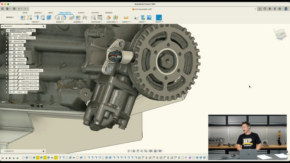
| 06:53 | So if we just jump over to Fusion 360 here, you can see I've got the little hub there modelled up in the position it'll be and then we have the harmonic damper or the crankshaft pulley on there, that drives the alternator and we'll just get into modelling that speed wheel or tone wheel and show you how that's done so just before we get into that, I'll just make a call now, if you have any questions throughout this process, anything at all related to basically CAD or what we're talking about today, feel free to ask them in the chat and I'll do my best to answer them at the end once we've modelled the part. |
| 07:40 | So just to get started, what we're going to do is start with a sketch on this surface here on the front of that hub adaptor there. |
| 07:51 | So this is going to be just a single sketch and a single 3D feature to create this part. |
| 07:57 | But this sketch is going to get a little bit involved just to create all the details. |
| 08:04 | So if we start by just projecting this inner circle here and this outer one, and we'll just project each one of these holes as well just so we can get the centrepoints for those and we'll include those in our profile. |
| 08:20 | So I just naturally opened the project tool quite quickly there, that project tool can be found under this tab here or you can click quick key P to open that up and if we project those parts you kind of see them in purple on the screen there, just like that. |
| 08:43 | So now I can use those features in the profile. |
| 08:46 | And then it's just going to be a matter of sketching a few circles to start with and then building those details into it so I'll start here by sketching a circle on here which kind of roughly matches the outer diameter of the pulley here, I don't want to go too much bigger than that, there's no need really but it needs to be a bit bigger than that so there's no interference issues with the hall effect sensor when I install that. |
| 09:20 | So we'll make that about 180mm, sorry 150mm should be about right and then we'll also sketch another concentric circle so concentric meaning they just share the same centre point and we'll sketch that circle inside here as well and we'll make that 135mm so that means, this will make a bit more sense in a moment but basically the teeth will span between these parts here. |
| 09:53 | So the next step from here is going to be sketching a line using the construction line type over here and we'll go from that centre point and we'll go through one of these holes and out to the edge here. |
| 10:10 | Pressing escape to just cancel that tool, I'll just use the concentric constraint between that construction line and the centre of that circle so that's fully defined now and just that line goes from the centre out through that circle to the edge. |
| 10:24 | I'm going to use a similar method to basically sketch in the sides of the first tooth so if I use, draw 2 short lines, I'll actually just take that off the construction line type 'cause I want these to be included in the final profile. |
| 10:44 | Sketch 2 straight lines from the outer circle to the inner circle here, roughly kind of lining up with this inner point, or I could actually do it right into the inner point might be better, save a few process into here and then I'm just going to trim off the parts I don't need there. |
| 11:07 | So just cut off those parts so we're only left with the sections of line between those 2 points and I just want to make sure that these lines also go straight in through the centre of the circle which it does look like they are, if I drag it around you can see it kind of follow that arc. |
| 11:32 | So from there I'm also going to use the trim tool to just remove, oh I lost that line just then. |
| 11:40 | I'm going to use the trim tool to remove the outer bit of the circle outside this tooth, this will make a lot more sense as we build the rest of the model but if I do that then I can use the mid point constraint between the end of this line on that point there and then this point here and that will basically allow me to then space the tooth equally about that point so if I use this, because those lines are on an angle to each other, it's going to automatically give me an angle dimension between those 2 lines and we're going to put that at about 4° and I can see I've got a bit of an issue here with this line here isn't actually going through the centre point so I can just fix that now with the coincident constraint and you can see that snap together and now that's fully defined in black so we always want to make sure the sketches are fully defined if possible to avoid unintentional errors creeping in and keep things, everything defined correctly and with correct references so if we ever go back and update a dimension, the rest of the model will hopefully update automatically and we won't have anything that we need to go on and fix, it just makes everything more efficient, more accurate and more reliable as well and it just saves a lot of headaches in the future. |
| 13:05 | So with that done, the next step is going to be using the trim tool again to just remove these 2 inner sections and then we'll just use the fillet tool here just to round these two parts here. |
| 13:18 | 2mm radius probably OK, we'll try one see how that looks. |
| 13:23 | 2, we'll leave it with 2 I think. |
| 13:27 | And do that, so that there we have one tooth created, so obviously if we worked around the whole thing and created all the other teeth, this is obviously going to take quite a while so in the interest of efficiency we'll use the circular pattern tool found under the create tab here, select that and then we can select the objects that we want to copy so we'll select the fillets, the edges of the tooth, the outer edge, down the other side the same thing and then for the centre point, the centre of the circle obviously. |
| 14:02 | So this distribution here, we want it to be full to go around the entire circle but we also want to be able to suppress some of the patterned parts, so we'll explain why in just a moment but we'll select that and then we want 36 teeth so you can kind of see that has brought that but what we're going to do is create a 36 minus 2 trigger wheel so basically there will be 36 teeth or there would be 36 but minus 2 so our ECU can basically tell the home position each time. |
| 14:41 | So if we got this suppression thing select here then we can just remove these two teeth there and that will exclude them and that basically makes our 36 minus 2 pattern. |
| 14:56 | There's all sorts of different trigger wheel setups with 36 minus 2 or 12 minus 1 or lots of different setups, it's not my area of expertise, I won't get into that there but this will work perfectly fine for our application. |
| 15:14 | So clicking OK and you can see that that is copied all the way around there. |
| 15:20 | Basically saving us all that time in doing that ourself. |
| 15:25 | So we can move on from here and basically all we want to do now is if we just look under the overhead camera is sketch these parts here so we can remove some weight for it. |
| 15:36 | Depending on how you make these, one thing I should mention is obviously for it to create a magnetic field the material needs to be magnetic so it needs to be a ferrous metal being something like steel, you can't make these out of aluminium because it won't work with the hall effect sensor so because it is steel and it needs to be relatively thick, again depending on how you design it, it ends up being relatively heavy so if you can remove material out of it in a pattern like this then it goes a long way to saving weight and obviously we don't want to add significant weight to the crankshaft of the engine that's just rotational inertia and if we can avoid that it's best to do so. |
| 16:29 | This part here will be machined out of aluminium 'cause it doesn't need to be magnetic but obviously there are some concerns around using dissimilar metals in contact with each other and there will be accelerated corrosion of the steel part I think in this case so we just need to make sure essentially that this part is coated and protected from that corrosion. |
| 16:55 | It is something we'd want to avoid in this case, if we have to replace this part because it corrodes it's fairly easy to do that, it's going to be pretty cheap but it is something that we want to keep in mind moving forward. |
| 17:11 | But yeah so in this case I've done this design to remove the weight like this so it lines up, the connecting part here lines up with the PCD of that 6th stud, in interest I think that'll give probably the best kind of strength to the part, not that it really needs it anyway. |
| 17:32 | So we'll copy that kind of pattern onto our model here. |
| 17:38 | For the inner diameter of the circle we're just going to be using approximately this surface here that's in line with the outside of the hub and we'll also just sketch another circle here and that there will be 115 diameter and then we are going to sketch the other circle here, we'll just make this one a construction circle so we don't end up using it. |
| 18:15 | But I want to make this here, oh got to find the dimension on that. |
| 18:21 | The diameter of this circle, I'll actually delete that projected circle. |
| 18:26 | Oh I've made a mistake. |
| 18:30 | Delete that projected circle. |
| 18:33 | If I can. |
| 18:35 | It's not happy with that, I'll just dimension this circle, oh sorry, trying to do it too quick. |
| 18:45 | Dimension this inner circle here at 80mm so that matches that and then we're going to basically sketch between these 2 profiles to create the same pattern that we have here so I'm going to start by using another construction line through this hole out to this outside circle here and use the coincident constraint of that construction line through that circle and that will then allow me to create, take the line type off construction and then use this, a line again, 2 lines from the outer circle there to the inner one and then again I want to make those coincident with that inner point so they are basically in the radial direction straight in towards the centre of that circle. |
| 19:47 | And then I will dimension the angle between those and those construction lines through the circle at about 5° so if you can imagine, there'll be another line over here, that means there'll be 10° of spacing between them and that fully constrains those lines. |
| 20:09 | So from there, I will just trim the parts of the outer circle that we don't need and the inner one as well. |
| 20:24 | Just to make things a bit easier on the next step. |
| 20:30 | Then we're just going to use the fillet tool to round those corners so we don't have any sharp edges. |
| 20:39 | 4 or 5mm looks about right and then so there we have one and then it's going to be the same process there of using the circular pattern tool and selecting those objects and then we can just select the centre point again and distribution, we want it to be full and this time we're just going to copy that 6 times around and we don't need to use the suppression feature at all for that either so we can just see that those have come up and shown in blue so the best thing here is just going to be to, oh Fusion 360's not too happy with that, it's just loading, the best thing here would be to figure out why those aren't fully defined so I just tried to drag the sketch a little bit there just to see what was going on, doesn't look like it's going to let me. |
| 21:38 | Things are just moving a bit too slow but if you could drag it and just determine what dimension it's missing, add that in so it becomes fully defined before moving on, that's really the ideal situation. |
| 21:51 | But that basically completes the sketch there so I'm just going to finish that sketch, jump back in here, just want to show that sketch, oh no that sketch would be under here, down the bottom. |
| 22:11 | And then I can use the flange tool under the sheet metal tab and I prefer using the flange tool in this case rather than extruding that because then that will create a sheet metal body and then we can basically make a flat pattern and a DXF from that a lot more simply. |
| 22:28 | So if we use the flange tool here, and then select the profiles that we want to include, that's just the outer profile so that will basically be a spigot fit onto the hub there and then we can go around here, if we'd made that a construction line this would have selected these ones for us. |
| 22:55 | But we'll just work around here and select each of those teeth, not really the most efficient way of doing it but we'll get there in the end. |
| 23:06 | And that's just selecting the profiles for the flange tool and then we can use the side preference here to determine what side that's been made on. |
| 23:21 | The bodies are hidden so there. |
| 23:24 | So yeah we want it to create, use the side one there so the material is added to the model in this position outwards so we don't have any interference. |
| 23:35 | If it happened like that it would go down into the hub surface there with side 2 so we'll use side 1 in that case and create a new body from that, select OK and that should finish it up. |
| 23:49 | It's just working a bit slowly 'cause I've actually been modelling some other parts within this assembly as well. |
| 23:59 | But there we have that but the thing here is we just want to make sure that that part is thick enough so if I jump over to the sheet metal rules for this and we go to steel, oh stainless, it must be under stainless steel, I'll just edit that and we'll just change this to be 5mm thick. |
| 24:22 | And click save. |
| 24:25 | And then you can just see the thickness of that has been increased there. |
| 24:29 | So yeah if we just look back at the overhead camera, we want it to kind of have some thickness to basically get a strong voltage signal from that so can't quite see there but on the end of this there's a small circle there that's probably about 4 or 5 mm in diameter and that's the actual sensor so the more thickness, if this was too thin the signal we'd get wouldn't be so good. |
| 24:56 | And that's kind of why it needs to be thicker but there is a kind of alternative to this, just bear with me a moment. |
| 25:08 | So just looking at this design here, this is one that Brandon sent me, I think this is off Aero Dave's Instagram, I think Dave Higgins is the name, who we've had on the podcast before and this is, does some awesome CAD work here, so you can't see to much here but this is kind of an alternative to this design which would in this case be quite a bit lighter so this is actually a thinner part that is then bent, all of these teeth are bent to come up here to basically help with the signal there so you don't need to use a really thick design for that, just keep things a little bit lighter weight and avoid having to use something like a 5mm thick tone wheel, you could probably reduce that weight significantly which is definitely good. |
| 25:59 | In this case that's bolted to a motorsport style upright, he's got his hall effect sensor here and yeah that has been used obviously as a wheel speed sensor in that case. |
| 26:12 | But anyway that basically shows you the modelling process of that using the circular patterns in the sketch thing. |
| 26:19 | If I just delete this and I'll just jump forward in my model because obviously I already designed this, this is something I was working on for myself. |
| 26:30 | I can see that I have that model in there and then also got the hall effect sensor in that part as well so that's basically how it's going to end up looking. |
| 26:42 | I've designed this little bracket so I can still use the little sheet metal timing marks on the original thing and yeah that's basically how it's going to be in the end. |
| 26:53 | So like I said, I've worked on a little 3D prototype to be able to assemble that to the engine and basically make sure that's correct, I won't be running with that 3D printed part 'cause that's just printed out of PLA and with the temperature and stuff that just won't withstand that in the engine bay. |
| 27:11 | You could 3D print it out of something else, I think in this case I'm going to get it machined out of aluminium though and hopefully that should be a good solution to my crank trigger, missing crank trigger, I will then have one. |
| 27:25 | So just to recap, we've done a bit of an intro in these webinars to OnShape, Solidworks and Fusion 360 in the past, in previous webinars and we've been starting to do some topics like this as well just to support our CAD course, some little worked examples like this. |
| 27:45 | So we're doing this in a few different programs, OnShape, Solidworks, Fusion 360 and we did one in FreeCAD as well. |
| 27:54 | If there are any parts that you'd like to see modelled that we can do in a reasonable timeframe in particular programs that you'd like to see, make sure you let us know. |
| 28:03 | Otherwise, thanks for watching and we'll see you next week. |