357 | 3D Scanning Workflow - Start To Finish
Summary
Scanning a real object and bringing it into the virtual world can open up a range of design possibilities, but it's not always as simple as it sounds. In this webinar we'll cover the entire process, from scanning a real motorsport part, post processing the scan data and transferring our scan into CAD software for use. We'll also discuss considerations for each step and some tricks and tips.
| 00:00 | Hey team, Connor here from HPA and welcome along to another one of our webinars. |
| 00:04 | So, this week we're going to be talking about the 3D scanning workflow. |
| 00:09 | We're gonna give a bit of a demo, we're gonna talk about what's involved in taking a 3D scan from a part and then bringing that into CAD software for use in reverse engineering or scan based design moving forward from there. |
| 00:24 | So, we're gonna give a bit of a demo with our PL3 scanner and we're going to be scanning this here suspension upright or drop knuckle, we'll get into a little bit more about what this is in just a moment. |
| 00:37 | And while things are processing I might have a bit of time to just discuss some other 3D scanning related topics as well. |
| 00:44 | So, the reason we wanted to do this, cover this topic is we get a lot of people talking to us about 3D scanning and they kinda have a rough idea about what it is, but maybe don't understand quite what's involved in the process. |
| 01:00 | 3D scanning is becoming a very powerful tool, but it's also becoming more and more accessible, especially at the hobbyist level with our cheaper scanners coming out as well. |
| 01:10 | So, if you are completely new to 3D scanning then this will give you a little bit of insight into what's involved and also if you have some experience with 3D scanning before, you might pick up a few tricks as well. |
| 01:24 | And of course at the end there'll be time to answer some 3D scanning related questions or anything else related to CAD that I can do my best to answer at the end. |
| 01:34 | So, very quickly before we get started showing you the workflow process, we'll just talk about what 3D scanning actually is for those who aren't familiar with it. |
| 01:44 | So, it's basically the process of capturing data from a real object or environment and then converting that into a digital 3D model. |
| 01:54 | So, the 3D scanner basically uses a projector in the middle, it's projecting a light source onto the surface, well generally they all tend to work like this, the structured light scanners that we typically use for motorsport design work on this principle. |
| 02:13 | Projecting a light source from the projector onto the object and then the two cameras here will basically view how that light source lands on the object and from that they'll use what's called triangulation and be able to analyse the shape and build a 3D model from that. |
| 02:36 | And then some scanners also have an extra camera here and that allows the capture of colour texture as well. |
| 02:43 | So, they can capture the surface colour and finish of the part as well as the actual shape and geometry. |
| 02:52 | So, basically the data is collected into what's called a point cloud and then from there that data is processed and it's processed into a mesh file. |
| 03:03 | And the mesh file is basically the surface or shell of the object and that's broken down into many tiny little elements. |
| 03:10 | They could be triangular or polygon shape faces and then those faces are connected to each other with an edge and then at the point there's a node as well. |
| 03:20 | And there could be hundreds of thousands to millions of elements in a single mesh body. |
| 03:28 | And then that mesh can be brought into our CAD software and from there we can work with it. |
| 03:33 | It's a little bit of an issue working with mesh files in most CAD software, they're not the easiest files to work with, but the CAD software does have some tools specifically for that. |
| 03:47 | It's something that we've actually covered in another webinar before. |
| 03:51 | But our process today, our focus today is just going to be talking about the actual 3D scanning process to get that mesh file to be ready to bring that into CAD. |
| 04:02 | So, what is this part here and why would we want to scan it? So, this is from a company called Part Shop Max and this is a suspension upright or they call it a drop knuckle. |
| 04:15 | So, basically it's just the upright and where the hub mounts has been shifted up and the intent there is to correct the suspension geometry on lowered cars. |
| 04:26 | It also has a much shorter steering arm or steering knuckle there and that's great for quick steering, but also can give more angle for drift cars, more steering lock. |
| 04:41 | So, why would we want to scan this? This part has some pretty simple geometric features on it like the mounting bosses for the brake caliper or the hub there. |
| 04:53 | But in the middle of it it's kind of more of a regular shape that is a little bit less easy to model basically. |
| 05:01 | So, to be able to 3D scan it, we'd be able to get an accurate model of the part of that shape without having to spend a lot of time trying to match it as it is. |
| 05:11 | So, I wouldn't actually scan this part to reverse engineer it and recreate it identically as a solid model so I could manufacture it again. |
| 05:23 | Clearly, there's no point to go through all the effort to do that, they already sell this part and I doubt I could spend all the time remaking it to justify it being any cheaper. |
| 05:34 | So, you'd definitely just go and purchase a part off the original designer. |
| 05:38 | But the reason I would 3D scan it would be to use it for scan based design, which is where I would use it, bring it into a model or an assembly with things like maybe the coilover or other suspension arms, I could install a model of the hub onto it with the brake disc as well, and the brake caliper I wanted to use and then I could build a brake caliper bracket to mount the caliper in the correct space. |
| 06:06 | So, a really good reference as a 3D scan so we can then design new parts. |
| 06:13 | Another reason I might do it is to get really accurate measurements of where all the suspension mounting points are and then I could bring those into something, a software like Optimum G and use that in an analysis of the suspension geometry if I was designing some new suspension components or just using this on whatever vehicle I was using it on. |
| 06:37 | So, basically, I'll just run through the rough idea, the outline of the workflow and then we'll get into each one of the steps showing a proper demonstration of how it's done. |
| 06:51 | So, the first step is going to be setting up our parameters in our software. |
| 06:56 | And we also might want to calibrate the scanner at that stage. |
| 07:00 | And also in some cases we'll need to prepare the part with some surface treatments or applying positioning targets to it as well. |
| 07:12 | Then the next step from there is obviously going to be 3D scanning and capturing the data. |
| 07:18 | And when we have that data captured, we'll do what's called cleaning. |
| 07:23 | So, that's basically removing unwanted data from the digital model. |
| 07:29 | And then from there we might merge multiple scans together, which I'll show you an example of doing that with this part. |
| 07:36 | If we have multiple scans, at that stage we'll merge them together into a single file, a single mesh file, or a single scan I guess. |
| 07:46 | And then we'll align that scan with our workplace coordinate system. |
| 07:51 | And that's just gonna make our life a lot easier moving forward. |
| 07:54 | So, everything's lined up in our workspace. |
| 07:58 | From there we can then generate the mesh file from the point cloud. |
| 08:02 | And also possibly edit the mesh file as well. |
| 08:06 | But we'll look at that a little bit more as we progress through the example. |
| 08:11 | Then after that we can extract entities. |
| 08:14 | So, that's basically the geometric forms of the part, things like the holes and stuff, we can extract those forms from it using specialist software. |
| 08:27 | And that can also be done in our CAD software as well, which we've shown in another webinar but I'll show briefly today. |
| 08:36 | And then from there we can transfer the mesh file and the extracted entities over to whatever CAD software we want to work in. |
| 08:45 | So, I'm gonna start progressing through the demonstration and showing that workflow and if you have any questions come up that you might want to be answered I will drop them in the chat and I'll do my best to answer them at the end. |
| 09:03 | So, the first step we will jump into the software here. |
| 09:09 | And this is the peel.OS, so Peel operating system for the scanner. |
| 09:15 | And you can see here we have the option to open existing projects that we've been working on or start a new scan, which is what we're gonna do but first of all I'm just gonna jump down here into the options tab and here we have the length unit that we want to be working with and you just want to check that that's correct. |
| 09:34 | So, you can work in imperial or metric measurements here, we're gonna work in millimetres, it doesn't really matter what you work in, it just matters when you bring it into CAD in the end that as you insert that mesh you match whatever length unit you get so it comes in at the correct scale. |
| 09:53 | So, I'll just hit Ok there and then start a new scan. |
| 10:00 | So, first up like I said we've got our parameters. |
| 10:03 | So, we've got these little check boxes here and this is fairly representative of what most scanning software will be like. |
| 10:12 | So, these check boxes we can choose based on the features of our, or the characteristics of whatever we're gonna scan and then these help the software automatically apply some parameters to our project. |
| 10:29 | So, in this case it's just a matter of choosing whatever's suitable for our part so here this first one is the object size, tiny, small, medium, large or human body in this case. |
| 10:42 | We're gonna be choosing small in this case, because the object size should be larger than 200 millimetres but smaller than 600 millimetres so our upright fits right into that gap so we'll leave that as small. |
| 10:55 | For the detail as well, some options here. |
| 10:58 | So, this is basically gonna control, yeah, how much detail we need. |
| 11:02 | We'll get into the resolution in just a moment. |
| 11:05 | But in this case fine seems pretty appropriate. |
| 11:09 | There's quite a lot of details on this part, but nothing super super fine. |
| 11:15 | There are a few threads but we don't really need to capture them in this case for what we're going to use the part for. |
| 11:23 | So, if we want to go much more detailed that's obviously gonna increase the resolution here and our file size is going to be a lot larger, because of it and it's gonna put a lot more load on things. |
| 11:36 | We just wanna keep things moving along if we don't need that extra detail. |
| 11:40 | And saying that, you always want to have more detail than you need rather than the opposite and having not enough detail. |
| 11:49 | So, yeah it's better to have it and not need it than need it and not have it. |
| 11:54 | The next one here is the output and that's basically when the mesh file is generated, how refined the mesh will be. |
| 12:04 | So, it's the same kind of idea as the detail. |
| 12:08 | A watertight mesh is something that has no holes in it or anything and you can take that straight from there and say 3D print it or something like that. |
| 12:16 | We don't need our part to be like that. |
| 12:19 | It doesn't matter if there's some holes in the mesh really, within reason. |
| 12:23 | So, in this case we'll just keep balance, that's a pretty good kind of medium spot between them. |
| 12:31 | We don't need a massively detailed file size but we would like to keep some of the detail in there as well, because we're going to pick up on some of these features so it's good to have an accurate representation of them. |
| 12:43 | And the final one here is the colour, if we want to capture colour. |
| 12:47 | It's not really going to do us much use on this part, cos it's basically just been anodised or zinc coated gold. |
| 12:57 | Yeah, it's not really going to be much benefit to us so we won't be capturing it in this case but if you wanted to there's some options here as well. |
| 13:08 | But we can jump down here if we want a little bit more control over things and toggle advanced parameters. |
| 13:15 | And here we can see what the actual resolution value here is. |
| 13:19 | So, if we think about this as the minimum amount of detail that can be captured. |
| 13:26 | So, you might not be able to see on this too much, but there's a kind of rough cast surface finish over this, the main body of the part and then these surfaces have been machined as well for a little bit more better and more accurate surface finish. |
| 13:44 | So, if we look at kind of the surface roughness there, that would be a lot smaller than one millimetre in most cases. |
| 13:52 | So, if we have one millimetre resolution we're going to miss out on a lot of that kind of texture which isn't necessarily a problem, it's not going to be a problem at all in this case. |
| 14:03 | But if you have really small features that you're trying to pick up on like threads for example, let's say the thread pitch is half a millimetre or something really fine, you're obviously not going to capture that with one millimetre resolution. |
| 14:20 | So, that's just something to consider there. |
| 14:23 | For this part we'll just use one millimetre for the resolution. |
| 14:26 | Typically, if you're doing really detailed mechanical parts you could go lower than that, down to 0.5 or 0.2 or something like that. |
| 14:35 | Really precise it can go a lot more than that as well. |
| 14:39 | Or really fine resolution I should say, precision would be more the accuracy, which shouldn't be confused with the resolution. |
| 14:48 | But we'll just keep it at one mil for that. |
| 14:51 | On the other side of the spectrum if you were working on say scanning a body panel on a car, you probably don't even need one millimetre resolution, you could bump that up to two, three, even up to five millimetres in some case. |
| 15:07 | And that's going to keep the file size down and keep your computer working through it very quickly, which is going to be beneficial if you're scanning large areas for sure. |
| 15:18 | We'll keep it at one millimetre in this case. |
| 15:21 | The scanning area here, this is based off the object size that we chose. |
| 15:26 | So, generally we're going to want to maximise this to 100% and that's basically the field of view that as the scanner is looking, the size of the area it can see. |
| 15:38 | Generally, we'll want to maximise it basically to help with the scanner positioning so it can see as much as possible in the frame and also be able to collect the biggest amount of data possible. |
| 15:50 | In some cases like now we might want to reduce this maybe to let's say 70% and basically, what that's going to do is mean we're only using 70% of that field of view and that can just be beneficial if we're scanning smaller parts on the benchtop like in this case just to mean we're not going to get too much of whatever's happening in the background and it'll make it a little bit easier to just get rid of what we don't want later on. |
| 16:24 | And some other things here, other more advanced resolution settings. |
| 16:29 | This one basically optimises the mesh resolution so in the end we have areas of high detail on the part will have a finer resolution and more simple areas will have a more coarse kind of resolution so it just helps keep the file size being smaller while still including as much detail as possible and we're not going to need to use targets for tracking on this part, because it has plenty of geometric features to kind of pick up on. |
| 16:59 | So, we'll leave it at that for now anyway and we'll just skip over to the next step. |
| 17:04 | It's just prompting me to plug in the scanner so I'll just do that. |
| 17:25 | So, over on this page as well we have the option of calibrating the scanner which I'll just mention really quickly. |
| 17:34 | So, this here is like a calibration board and we can see on my computer screen it's just kind of prompted that. |
| 17:42 | So, this basically is just a way of dialling the scanner in, making sure you're capturing accurate resolution, sorry accurate data and then also it'll adjust for your lighting conditions and things like that as well. |
| 17:56 | I've actually calibrated the scanner in this environment very recently. |
| 18:01 | In this case I'll just skip this to continue on with our workflow but that's definitely something that you want to do. |
| 18:09 | If the scanner has been moved around a bit, it hasn't been calibrated recently, your scanner settings have changed or you're scanning in a different lighting environment so I'll just hit skip there. |
| 18:21 | We also have some options here on the shutter speed as well. |
| 18:26 | In this case we'll just keep it on the automatic shutter but you can tailor the shutter speed of the scanner for dark surfaces or bright surfaces as well just to make sure the exposure is correct and it can capture the data properly, but it's not going to be a problem. |
| 18:45 | And here we've got quite a nice well lit environment but we're not working outside in sunlight for example or with the lights off or scanning anything too dark. |
| 18:57 | So, with that we should be all ready to just get into it. |
| 19:10 | So, from here we can just get our scanner and there's the option in the workspace up here to start the scan or the peel actually has a little touch screen on the back so we can just start the scan from there as well. |
| 19:28 | Basically, all we're going to do is just point it at the target and we can see in our workspace on our computer that it's starting to capture the object there as well and I've just got this on a turntable, save me having to walk around it so I can just slowly turn the object around and capture the data from all the different angles. |
| 19:53 | And I can move the scanner as well and you can see that it just tracks the movement on the screen. |
| 20:00 | And basically, what you're trying to do is work around the object and just capture data from all different angles. |
| 20:07 | You can see, I'll stop moving for a moment, you can see the kind of yellow areas of the scan on the screen and that's basically where you've captured a little bit of data but not too much yet. |
| 20:18 | And you can see the holes on the model in the screen as well, like that top edge that's going up to the strut mount. |
| 20:26 | At the moment I haven't got that yet, but as I work around the scanner we'll start to capture data from that surface. |
| 20:35 | And you'll just see that kind of filled in. |
| 20:39 | So, it's giving you a visual kind of aid to show you where you have and haven't captured data from. |
| 20:47 | And on the back of the screen here which I can't really show you, there's a little green bar at the top, it's just gone red and points and arrows and that shows me the distance that I need to be from the scanner. |
| 21:00 | So, I'm just trying to keep the right distance, if I go too far away it'll struggle to capture data and if I go too close, then the same will happen. |
| 21:13 | And on the display on the screen you can see the same thing, all those green lines are showing a pretty good distance, it's in the kind of optimum range for the scanner. |
| 21:24 | You can see if I move back it goes blue, so that's too far away. |
| 21:30 | And if I move in, see a bit of red starting to form there and that's getting too close. |
| 21:40 | So, we just want to keep making sure we've captured all the data from the different angles. |
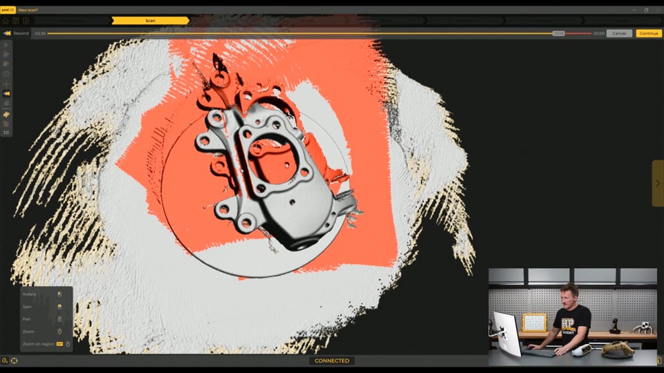
| 21:56 | And what we're going to do is scan the top side of the part, or the outside I guess, like this, and then I'm going to also move on, oh, we've got a bit of an issue there. |
| 22:10 | So, see, it's kind of mistaken the model, so what I'm going to do is this rewind feature, just going to go back and you can see there that something's happened, it's just kind of got an error, but I can use the rewind feature on this and just jump back and remove whatever happened there. |
| 22:31 | So, it's basically just removing frames, because it's going around capturing lots of frames like a camera. |
| 22:41 | So, it's pretty easy to just kind of rewind and remove that. |
| 22:45 | Not all software will have that option, but in this case we do. |
| 22:51 | Hopefully this doesn't take too long. |
| 22:53 | But basically what I'm going to do is capture this top side and then I'm going to remove what I don't need and then start a new scan, flip it over, scan the other side, and then I will then merge those two together. |
| 23:07 | So, let's just have a look here. |
| 23:11 | There's a lot of noise and stuff shown here, this is just kind of the raw point cloud, just showing me a rough idea of what it all looks like. |
| 23:19 | And it looks like we've got kind of everything pretty good on the outside, and you can see all the noise floating around and stuff and that's all very easy to remove as we move into the next cleaning step there too. |
| 23:35 | Got a little bit of something funny happening here. |
| 23:40 | I might just try to jump back a bit more. |
| 23:50 | That was quite far back. I'll just leave that as it is. |
| 23:55 | Didn't pick that up earlier, but I might be able to just jump in. |
| 24:01 | So, I'm going to basically cut this off and come back and just redo this part because I'm not happy with what's happened here. |
| 24:09 | You can see on the steering arm I've got a bit of an issue. |
| 24:12 | So, if I jump forward a step, then first of all we can just remove the background from the parts. |
| 24:19 | I'm just going to click this and select on the top of the turntable and just delete everything under the surface there. |
| 24:28 | OK, continue. That will just remove that there. |
| 24:33 | And then if I have, this is the selection settings here, and this one here means if I select somewhere on the part it will select everything that's connected to that. |
| 24:44 | So, hold the control button and just click on the part. |
| 24:48 | Let's see that we can, yeah, just got that. |
| 24:51 | And then I can go, I could either invert the selection now and delete everything else or I can use this keep only function here. |
| 25:00 | And continue and that'll keep just what I selected. |
| 25:03 | But I really want to get rid of this issue here. |
| 25:08 | So, what I'm going to do is change the selection there to the rectangle selection and just going to orient it in a way that I can just trim off what I don't need there. |
| 25:25 | It's probably a nicer way of doing this, but this will work. |
| 25:33 | And I'll just go delete. Remove that. |
| 25:39 | So, I'm going to have to now come back over and just fill in that gap there. |
| 25:44 | So, if I jump back here to the scan tab, then I can hopefully re-find the tracking. |
| 25:55 | So, the scanner needs to figure out where it was. |
| 26:11 | Which is a lot easier if you're using positioning targets. |
| 26:34 | Not wanting to pick it up. |
| 26:44 | Try it one more time and if not I'll just redo it. |
| 26:54 | Alright,, that's not wanting to do that. |
| 26:56 | What I'll do, so I'll move on to the next scan and I'll try to fill in that area on the other scan as well. |
| 27:03 | So, if I go back over to the clean one, cancel that, don't need to remove any more. |
| 27:10 | I'm going to go down here and I'm going to add a new scan. |
| 27:13 | Then what I'm going to do is just turn the part over on the table, turntable. |
| 27:20 | I should be able to get the top of that steering arm filled in there as well. |
| 27:23 | So, now I'm just trying to do the same thing and I want to scan the back of the part and get all of that data. |
| 27:31 | So, same thing, start. |
| 27:38 | And then again, just a matter of moving around. |
| 27:43 | And it might pick up my hand because I'm just spinning this around, but it's pretty easy to remove that in the cleaning stage. |
| 27:53 | Just make sure I get a good amount of that steering knuckle. |
| 28:03 | And capture all the parts that I wasn't able to get in the first scan. |
| 28:12 | I wanted to show doing this without any kind of surface sprays on the more shiny surfaces or any positioning targets, just to show that if you have a part that has some geometry like this, then it shouldn't be too hard to be able to scan it. |
| 28:34 | And it's doing a pretty good job of picking everything up, hasn't lost any tracking yet, other than when I stopped it before. |
| 28:45 | Just make sure I've got everything, it's looking pretty good. |
| 28:51 | Just paused it. |
| 28:55 | And looks like I've got everything pretty good there. |
| 29:00 | So, there are some tools you can use here, like the clipping plane, and that can remove kind of the surface, anything under that surface level. |
| 29:10 | But in this case it's quite easy to remove that in the cleaning step. |
| 29:15 | So, here, we're just going to remove the background. |
| 29:18 | Same thing, just click on the turntable. |
| 29:24 | Looks pretty good. |
| 29:28 | Actually, maybe not so good. |
| 29:33 | There we go, that's better. |
| 29:35 | So, everything in red, that side will be removed, and we could come in here and just adjust the height of that. |
| 29:44 | That'll be fine. Hit continue. |
| 29:46 | And that'll just remove everything we don't need. |
| 29:49 | And then I'm just going to do the same thing again, make sure that connect selection tool is chosen, and then select the part, and then just go keep only. |
| 30:02 | So, it just removes everything else that I don't need. |
| 30:05 | So, now you can see down here we have two scans. |
| 30:09 | So, one of the back and one of the front, and then the next tab here says merge on it, so we can skip to the next step. |
| 30:17 | And that's already done that. |
| 30:19 | So, up in the left hand corner here we have the different merge options. |
| 30:24 | So, if I had targets all over the part, then it would automatically pick up the targets and it would merge them based on the target position. |
| 30:33 | In this case it's used the align by surface best fit, so it's just basically looked at the geometry of the part and aligned it. |
| 30:42 | Or in this case you could choose this last one, which is the manual alignment and you basically pick three parts on each scan that are identical on both cases. |
| 30:57 | So, you can choose three points on this, well divided on different planes, and then you can jump over to the other scan and do the same thing. |
| 31:07 | And then that'll basically bring those three points together. |
| 31:10 | So, if you've chose three well divided points in different kind of planes, it'll bring that together pretty good. |
| 31:17 | But in this case, surface best fit seems to look Ok. |
| 31:23 | It's not great, but rather than spending more time on this, we'll just keep things moving and I'll continue with that. |
| 31:35 | I would definitely like to come back and redo that, but in the interest of keeping things moving forward just for this webinar, we'll keep moving. |
| 31:44 | So, if I hit Ok, that just locks in the positions of those two and we'll jump over to the next step here. |
| 31:50 | And that's just saying that this will delete the original scans as it combines it into a single scan. |
| 31:57 | We'll just hit Ok on that. |
| 31:59 | And it's just merging those two scans together. |
| 32:03 | So, while that's doing that, I will just mention a few other kind of things we've got here. |
| 32:11 | So, these are little 3D printed parts, which are just little positioning target blocks. |
| 32:17 | So, in this case, we've just stuck positioning targets to a 3D printed part. |
| 32:22 | And I have three of those. |
| 32:23 | And for some parts that don't have so many geometric features like this one here, I would just stick those on the turntable around them and the scanner can kind of use those as positioning. |
| 32:34 | And then after I'm finished, I can delete them out of the model. |
| 32:37 | But it will just help tracking as you're moving around. |
| 32:40 | I was scanning a piston in here the other day. |
| 32:43 | Pistons, because they're such a perfect circular shape, it's good to use things like these to kind of show the scanner the different features as it moves around. |
| 32:55 | So, that's one option. |
| 32:57 | And then I just also want to touch on here these, which are also little parts that we've 3D printed. |
| 33:03 | And these are what you'd call podiums. |
| 33:06 | And basically, it's just a little pyramid shape that you can sit on the bench, and then if you have a flat part, you can sit it on top of, say, three of these, and it will just lift it off the surface you're scanning on. |
| 33:18 | So, it makes it really easy to remove that surface when you're finished, because they come up and it'll be unlikely that the scanner will be able to capture that top surface under there. |
| 33:31 | So, quite easy to remove the background if you're using those. |
| 33:37 | So, this next step here is the alignment. |
| 33:40 | So, in this case, we want to align the scan with our workplace coordinate system. |
| 33:46 | And this just makes it really easy as we move forward and bring that into our CAD software to have everything aligned in a kind of good location from the start. |
| 33:56 | And it's never going to be perfectly aligned from scratch, because basically when we start scanning it, we could be doing that from any angle. |
| 34:05 | So, this step is always really going to be necessary. |
| 34:09 | The peel.OS software makes this pretty simple. |
| 34:13 | So, there's a few different ways you can do this, but basically we just want to constrain the part in three dimensions. |
| 34:20 | So, what we're going to do here is we're going to click this, which is the x-axis, and then it's showing this entity here, which I mentioned before are kind of the geometric forms of the part. |
| 34:31 | And we're going to use those forms to align this part to our coordinate system, because that kind of makes the most sense. |
| 34:38 | So, we're going to use a cylindrical entity of the part to align with that x-axis. |
| 34:45 | And what makes sense to me is using the central hole here for the wheel hub. |
| 34:52 | I'm just going to choose a nice part of that, and that will automatically kind of find that cylinder surface. |
| 35:01 | And then from there, we can lock that. |
| 35:09 | I'm going to cancel that. |
| 35:11 | Didn't really do it nice. |
| 35:13 | There we go. |
| 35:14 | So, that's now aligned with the x-axis, and we can flip that so the x-axis is facing the other way, and then we can lock that there. |
| 35:25 | Next,, it makes sense to do the yz-plane, which is at the base of the x-axis. |
| 35:33 | And then that plane will allow us to select a planar entity, so that entity makes sense to be this front surface here. |
| 35:42 | And we can just select that. |
| 35:44 | So, I'm just holding Ctrl there and then choosing some triangles basically, or mesh elements on there, and it's just recognizing that surface. |
| 35:56 | I'm happy with that, so I lock that. |
| 35:58 | And then I just need to find one more part. |
| 36:00 | So, if you think about this part, this surface here is going to be aligned kind of with the inside cylinder there. |
| 36:09 | So, this strut surface here is likely going to be at a right angle to that surface. |
| 36:16 | So, for the last one, I'll click this other plane and then set that planar surface to the strut mount there. |
| 36:25 | And that's just going to set that parallel. |
| 36:28 | I'll just flip that, so that's aligned the part with the coordinate system. |
| 36:33 | And then if I hit lock, all of these are greyed out and the part is locked in place in that alignment. |
| 36:40 | And then I can just move through to the next step. |
| 36:43 | So, now we have our mesh and it's basically asking me for, these are the improvement tools, so I can do some more editing on the mesh if I wanted to here, and tidy it up a bit. |
| 36:55 | There's definitely some issues, which like this hole, I would have rather gone back and re-scan it. |
| 37:02 | But in this case we'll just keep moving forward. |
| 37:07 | We've still got a very usable scan for what I said we'd use it for, which is really just using it to design other parts around. |
| 37:16 | So, we can also take some measurements here if we wanted to, but we'll push on forward. |
| 37:22 | The next tab would be colorize, but we didn't capture color texture, so that's not going to be an issue for us today. |
| 37:29 | So, from here we could just export the scan as a mesh, which I will do. |
| 37:37 | I'll just throw it onto the desktop. |
| 37:42 | And we'll just call that Part Shop Max 86 Upright Scan. |
| 37:54 | And that's just saving that as an STL file, there are some other options, but that's just a simple mesh file there, so I'll just save that. |
| 38:03 | What I'm also going to do though is export the mesh to peel.CAD. |
| 38:07 | So, this is kind of an extension software from this peel OS system, and it's a bit more expensive to use as well. |
| 38:15 | But this is basically Peel's reverse engineering specific software. |
| 38:20 | So, you can see we've just jumped into this now with our model. |
| 38:25 | And it looks just like most CAD software does with the workplace in the middle of the model. |
| 38:32 | We've got kind of a navigation panel here, views down the bottom, and then all these tools up here that we can work with. |
| 38:40 | So, up in the corner here we have the alignment ones, which we've already done in our Peel OS, so we don't need to do those. |
| 38:48 | And then we have our entities, which is what we're going to work with in a moment. |
| 38:53 | I'm just going to unplug the scanner, because the fan's running, it's quite noisy. |
| 39:00 | And then we have some more tools here, we can do some measurements, and more mesh editing tools here. |
| 39:07 | And then we have some transfer to CAD software options at the end here, which we're going to use in just a moment. |
| 39:16 | So, what I want to do at this stage is I want to extract entities from the part. |
| 39:22 | So, things like what we've got here as planar surfaces or cylindrical entities, which are perfect for the likes of this internal hole or the other holes on the part. |
| 39:34 | And if I can extract those using this software, it just makes it a little bit easier than in our CAD software. |
| 39:41 | And then when we go into CAD, we can use those as surfaces of the part or features of the part to use when we're designing our other new parts, for example. |
| 39:52 | So, if we jump in here, I'll just drop this down so we can kind of see what we create. |
| 40:00 | So, we're just going to start with a cylinder. |
| 40:03 | Actually, sorry, we'll jump back and we'll start with a plane. |
| 40:07 | So, we just want to create a planar surface on the front here, and it's just as simple as selecting that. |
| 40:14 | That's just going to create a datum plane on the front of the part, and we could just hit Ok. |
| 40:20 | We could name that something to kind of keep track of things. |
| 40:23 | We'll hit OK there. It's just automatically jumped in to create another one. |
| 40:29 | And we'll do that in this case, and we can select, try to select anyway, some back surfaces here. |
| 40:45 | So, I can just click on some kind of well-divided points around here on these back kind of recesses for washes, I guess, with the hardware that will fix the wheel bearing or the hub to the front there. |
| 41:03 | And the main thing here is we want to go into constraints, and then we want to set this as normal to the plane that we just created before. |
| 41:14 | So, basically what that's going to do is be parallel to the first plane that we created, because it's pretty fair to assume that the design intent of the original designer is to have this surface parallel with the surface at the back, since that hardware is going to be coming straight through and mounting to it. |
| 41:32 | We'll just hit Ok there. |
| 41:35 | And then we're going to move on and create a cylinder on that internal surface again. |
| 41:47 | There, and then the orientation there for that as well. |
| 41:51 | I'm going to set that to the plane just so it trues it up nicely to that plane, in those perpendicular in this case, just to keep everything correct. |
| 42:02 | So, when we come in and we're modeling these geometric shapes in our CAD software, they're going to be, we can use these planes and these features or entities to model these new parts, and it's going to keep everything nice and square and true to our coordinate system and make our life a lot easier. |
| 42:21 | So, that's just an example of a few there. |
| 42:26 | And we could also do the same and go around and get all these different surfaces and the holes as well, and that'll just help us a lot moving forward. |
| 42:36 | But that's kind of rinse and repeat from that point. |
| 42:39 | So, we'll just move on in this case. |
| 42:42 | So, what I'll do is I'll just save this again as the PLCAD file and hit save. |
| 43:00 | And then now I'm ready to open Fusion and I'm going to transfer this over to Fusion. |
| 43:08 | And then I'll show you also as we exported the mesh file before how we would bring that into Fusion. |
| 43:18 | So, we got Fusion opening up. |
| 43:27 | And then all we're going to do is go transfer to Fusion, say it's Fusion 360. |
| 43:33 | It's actually been changed to just Fusion now by Autodesk. |
| 43:36 | And we can see that that has brought that mesh file straight into our Fusion workspace. |
| 43:43 | And it looks pretty rough. |
| 43:45 | I definitely want to be doing that again, getting a bit better results. |
| 43:49 | But that's the reality of working through things in a webinar. |
| 43:54 | So, we'll see that we just had the mesh file there. |
| 43:58 | And I also want to select these entities and transfer those to Fusion as well. |
| 44:07 | And now we can see that we have some construction planes brought over there. |
| 44:13 | And then we also have a center line there. |
| 44:17 | If I zoom in, hide those two. |
| 44:20 | For the cylinder in the middle. |
| 44:22 | And then if I hide that under the bodies tab, we also have that cylinder there which is just fit to that internal diameter of the part. |
| 44:34 | So, we can move from there and move into using this part to, basically I'd save this as its own design file and then I'd insert that into an assembly with other parts like the wheel bearing and stuff and start assembling everything together to design some new parts. |
| 44:53 | So, that could be the end of the road there. |
| 44:57 | I'll just show you another option. |
| 44:59 | So, I've just opened a new design file here. |
| 45:02 | I'm just going to jump into the insert tab. |
| 45:05 | And what I would do is insert a mesh from my computer off the desktop. |
| 45:13 | And that's just set upright. |
| 45:16 | And I can insert that mesh. |
| 45:18 | And then there's the unit type here, needs to be set to millimeters because that's what we were scanning in. |
| 45:22 | And that's already nicely aligned with our coordinate system like we set up earlier in the peel.OS software. |
| 45:30 | And then that's another way of getting that in there as well. |
| 45:33 | I will just jump back into peel.CAD. |
| 45:37 | And I want to show two things. |
| 45:40 | If we exported the selected entities as a step file to the desktop. |
| 45:53 | And I'll just go PSM86. |
| 45:58 | And then if I jumped into Fusion and I opened that step file. |
| 46:05 | This is just a way that you'd get the entities in there. |
| 46:10 | That looks like it saved it as a SOLIDWORKS file. |
| 46:14 | Anyway, that worked. |
| 46:18 | And then you go here, mesh create, insert mesh. |
| 46:21 | And then select the STL from there. |
| 46:25 | And that will bring it in and it's brought it in with an alignment to those entities as well. |
| 46:32 | So, that's just how you'd do that. |
| 46:34 | If you didn't have peel.CAD for example where you can transfer straight to Fusion 360. |
| 46:40 | The other thing I just wanted to make a note of, I've got some verniers here. |
| 46:46 | And I just want to select just the cylinder entity. |
| 46:55 | And it says the diameter here is 75.569, so 75.6-ish. |
| 47:01 | And that's measured the diameter of this internal surface here. |
| 47:05 | And I just wanted to compare the accuracy of that to the real part here. |
| 47:10 | So, it should be noted that I didn't do the best job of scanning this. |
| 47:16 | And there's definitely some issues on this inner surface. |
| 47:19 | That could have been done a lot better. |
| 47:21 | And using targets is going to improve the accuracy quite a lot. |
| 47:25 | But yeah, we've got 75.6 odd there. |
| 47:29 | And I'll just use the verniers and measure that internal diameter there. |
| 47:37 | We've got 75.8, let's say, 7.8. |
| 47:44 | So, we are about 0.2 of a millimetre off in terms of accuracy on the inner surface. |
| 47:51 | And this is just a good way of making these entities and then using those to be able to check the accuracy of the part as well. |
| 48:01 | This could be done a lot better and I bet you could get that accuracy a lot better with that scanner. |
| 48:07 | If you increase the resolution as well, that's going to help as you go around there to be able to get a better surface and then hopefully that'll translate to some more accuracy. |
| 48:16 | Or like I said, using targets will help there as well. |
| 48:19 | But that's a very, still a usable scan depending on the application. |
| 48:24 | You could definitely improve that a lot though to make it look a lot nicer and yeah, help with the accuracy a little bit and fill in some holes and things like that. |
| 48:35 | But we'll leave it at that anyway. |
| 48:38 | Hopefully, that's given some insight into what's involved in the process. |
| 48:43 | We have done more webinars in the past showing how 3D scans are actually used in Fusion 360. |
| 48:50 | So, taking what we've done here and kind of moving forward with that. |
| 48:56 | But there are a few options at that stage. |
| 48:59 | Obviously, reverse engineering is one of them so that would be like recreating this part as a parametric model. |
| 49:06 | Or we might use that for scan based design or suspension analysis or something like that. |
| 49:12 | This process can be done faster or more simply, or you can also spend a lot more time and really get into the details and really tidy things up as you go through it. |
| 49:23 | It just depends kind of what your application is and how much you need certain details. |
| 49:30 | On that note, we are currently filming a 3D scanning course as well. |
| 49:35 | That should be out before the end of the year, which we dive into these topics in a lot more detail. |
| 49:41 | It'll give you a lot more understanding on what's really going on as well as a lot of other topics as well. |
| 49:47 | So, if you're interested in what we've done here today, definitely keep an eye out for that moving forward. |
| 49:52 | But I'll just jump in and see if there's any questions. |
| 49:56 | If you have any questions, drop them in the chat and I'll do my best to answer them. |
| 50:23 | Sorry, just having a bit of a problem with my setup here. |
| 50:40 | So, the Motor Journal said, "Have you mentioned the pricing of these scanners? Do you find a rotatable table and fixed scanner works better or freehand scanning?". |
| 50:50 | So, the price of the scanners, let's just talk that first. |
| 50:54 | This Peel 3 unit I think is around $10,000 US. |
| 51:01 | So, this is a fairly expensive unit. |
| 51:03 | Obviously, you can go a lot more than that. |
| 51:06 | I used to use a Artec Leo, that was about $40,000 US. |
| 51:11 | But I've also had really good results with things like the Einstar, which is around $1,000 US. |
| 51:20 | So, I would say for a hobbyist, the Einstar's a great place to look. |
| 51:26 | Definitely gives some really good results. |
| 51:29 | If you have the means, stepping up to something in this level or the likes of similar units in that price range, they definitely at this point, it does make a good difference in terms of accuracy, resolution, the features that you have available. |
| 51:47 | A lot of that value is in the software as well, and just the quality of the scanner, the support you get, things like that. |
| 51:56 | But you can get very good results with the cheaper scanners as well. |
| 52:01 | This is technically, Peel I think is of the Creaform, it's owned by Creaform and it is their kind of more entry level market I guess compared to the Creaform ones and that's another step up again from there. |
| 52:19 | But it doesn't mean you need to be working with something like this to get results like these, especially the ones I got today. |
| 52:26 | You could definitely get that with a cheaper scanner. |
| 52:29 | It just depends on the kind of processes you're using, what you're scanning, what you're using it for. |
| 52:35 | I find, so the turntable here with a fixed scanner works better or freehand scanning. |
| 52:42 | So, if I'm scanning a small part like this, I always put it on the turntable, it just means I don't have to kind of walk around it and get it from every angle. |
| 52:50 | I've never actually fixed a scanner on anything, I can imagine that works quite well. |
| 52:55 | I just think I like to be able to move around and still get the different angles. |
| 53:02 | If you have the scanner fixed here and you're spinning this around, then there's still probably going to be little areas that are going to be difficult to get. |
| 53:11 | Although, having the scanner perfectly stable is going to help with the tracking and accuracy as well. |
| 53:18 | I like having the freedom of the freehand scanning. |
| 53:23 | It just gives you, if you're missing a certain bit, it's quite easy to just go and get that. |
| 53:29 | So, that's kind of my view on it, but either way works well. |
| 53:34 | Again, it depends on what you're scanning. |
| 53:36 | Definitely for larger stuff, working around a vehicle or something like that, freehand scanning is going to be the way, unless you have some serious professional equipment. |
| 53:52 | Shashak MSH, "What CAD course for motorsports do you offer?". |
| 53:57 | So, we have our 3D Modeling in CAD for Motorsport course. |
| 54:03 | I won't bring that up now, but that's been live for, I think, coming up two years or so now. |
| 54:09 | That covers everything, and we do it from a direction of learning the core fundamentals of CAD and then being able to apply all the different modeling techniques from there, rather than just showing you, hey, here's how you model this part or this part. |
| 54:28 | We show you how you can model anything. |
| 54:30 | And we cover everything from solid modeling basics, sheet metal, working with assemblies and joints, and then everything above that as well, through to technical drawings or more advanced topics, like working with 3D scans or 3D printing parts, surface modeling, generative design, and also we touch a little bit into things like FEA and simulation, just as introductory topics to show what's possible past that. |
| 55:02 | So, I definitely recommend checking out that course. |
| 55:05 | Jordi might be able to drop a link to that in the chat. |
| 55:09 | So, yeah, we've got an online forum going for that as well, with people in there all the time asking questions. |
| 55:17 | So, if you have any extra questions during that course, jump in there and I'll do my best to answer. |
| 55:24 | Mikhail Bob, "Scanning a big object like an engine bay fender or even a whole car, what scanner can I use for that?". |
| 55:32 | That's a really good question. |
| 55:33 | So, actually here in the back we have our old Pell 2S, and this is the generation before the Peel 3. |
| 55:42 | It is probably slightly cheaper, more basic unit, and it's quite dated now. |
| 55:47 | This scanner here is designed or intended, the Peel 2S it is, not the Peel 2, is intended for small detailed parts. |
| 55:56 | And it would probably do a really good job of scanning this up right here. |
| 56:00 | But for a while this is all we had, and this is what we used to try to scan things like engine bays, body parts of cars, body panels and things like that. |
| 56:10 | And it was really, really difficult. |
| 56:13 | Basically, because the field of view is tiny. |
| 56:16 | So, as you're working along through an engine bay, it's only seeing very small parts. |
| 56:22 | So, you're capturing data really slowly and then it also affects how the scanner is tracking. |
| 56:27 | And it would just take a really long time unless you had tracking targets covering the whole thing, which is a bit of a pain as well. |
| 56:35 | I would look for, if you're scanning large things like engine bays, fenders, whole cars, things like that, I'd definitely look at something with a larger field of view. |
| 56:44 | And typically scanners will be marketed based on the size of the object that they're gonna be appropriate for scanning. |
| 56:54 | So, something in that medium to large range, not the scanner size itself but the object that you're scanning is gonna be appropriate. |
| 57:02 | So, I'd definitely keep that in mind. |
| 57:06 | We purchased recently a bunch of cheaper scanners to kind of fill that hole in what we're doing. |
| 57:14 | The Peel 3 is actually a loaner in this case. |
| 57:17 | And that does do larger objects much better than this, because the field of view is about four times as large. |
| 57:25 | But we also purchased, like I said, the more affordable ones. |
| 57:29 | We've got the Ironstar, we have the 3DMaker Pro Moose, we have the RevoPoint Range 2 and the Creality Scan Otter. |
| 57:40 | And when I was purchasing those, what I was trying to do was basically find something that would be more suitable for scanning the likes of engine bays where we could use something more precise like this for scanning small detailed parts to kind of like get the best of both worlds. |
| 57:55 | So, that's what I've got to say about that. |
| 57:57 | Field of view makes a big difference. |
| 57:59 | Something like the IronScan is great if you're looking for a more affordable 3D scanner. |
| 58:05 | Otherwise, in this market, the PL3 does a good job. |
| 58:10 | And if you're looking at options from the same company, for example, RevoPoint Range 2 is more focused towards the large objects whereas the POP 3, I think it is, is another option. |
| 58:24 | And that's focused, I think, towards slightly smaller objects. |
| 58:27 | And then they've probably got one below that that's for really small objects and a lot of detail. |
| 58:32 | So, there's lots of different options. |
| 58:36 | I probably just answered that next question. |
| 58:38 | "And what about the IronStar scanner for large and small objects?". |
| 58:42 | So, the IronStar is great for medium to large objects. |
| 58:45 | It would probably do okay with smaller stuff. |
| 58:48 | I haven't used it much on that. |
| 58:50 | In the software, like you saw at the start, there are options to kind of tailor the scanner's settings to the object size. |
| 58:58 | Not all scanners will have that, but a lot of them do. |
| 59:01 | And it basically just changes the resolution settings. |
| 59:05 | But having a larger field of view helps a lot with large objects. |
| 59:10 | But it's not necessarily that beneficial for small objects as well. |
| 59:15 | And in that mind, if you're scanning something large, you probably don't need as much resolution. |
| 59:20 | That's just going to make a huge file size. |
| 59:23 | If you're scanning something small, then you're probably going to need a lot of resolution to capture all the details and really do the part justice. |
| 59:32 | So, hopefully that answers those questions there. |
| 59:35 | And that seems to be it. |
| 59:37 | Like I said, we've got a 3D scanning course coming out soon. |
| 59:40 | And we're working on some more 3D scanning material with those more affordable scanner options like the IronStar that we just got. |
| 59:47 | So, keep your eye out for that. |
| 59:49 | If you've got anything that you'd like us to dive deeper into, let us know and we'll do our best to do that in the future. |
| 59:55 | But thanks for watching and we'll be back next week with another webinar. |
| 59:58 | Thanks. |
0:00 - Introduction
01:34 - What is 3D scanning?
03:51 - A suspension upright/drop knuckle
06:37 - Workflow overview
10:00 - Setting parameters in software
17:27 - Scanner connection & calibration
19:10 - Scanning process
29:15 - Cleaning up the scan
32:11 - Positioning target blocks
32:57 - Podiums
33:37 - Alignment
38:03 - Exporting
39:16 - Extract entities
43:18 - Opening in Fusion
49:56 - Q&A