365 | How To 3D Model & Print A Usable Part In Real Time
Summary
3D Printing can produce functional parts at a fraction of the cost (and time) of traditional manufacturing methods. Some people argue against CAD designing, saying it's better to "crack on" with manual fabrication to get the job done. Others claim that 3D printing is only good for prototyping and that printed parts can't handle the abuse of motorsport. While these arguments can be true in some cases, in many cases CAD and 3D printing can improve efficiency. In this webinar, we will prove how fast this process can be, by designing and printing a usable part in real time.
| 00:00 | Hey team, Connor here from HPA and welcome to another one of our webinars. |
| 00:03 | Today we're going to be talking, or having a look at 3D modelling and also 3D printing a usable part for our projects in real time. |
| 00:12 | So, we're going to basically show you how quick it is to model and print a functional part. |
| 00:18 | It's going to be a relatively small part so we can print it in real time. |
| 00:23 | But hopefully it'll give you a bit of an insight into how we can use CAD and also 3D printing to solve potential problems or little workarounds for any project car that you're working on. |
| 00:36 | So, let's just have a little look at the part that we're going to print under the overhead here. |
| 00:42 | So, it's going to be quite hard to see because they're really small. |
| 00:46 | But this is basically a little 3D printed part where we can use a rivet through this hole here and then a cable tie through this other slot here and it's just a nice little tidy solution that helps us with routing of hard lines or soft lines, hoses or wiring through the vehicle. |
| 01:07 | So, I'll show you a few images just in a moment there, just showing a little bit more detail about how we've used these in some of our projects. |
| 01:16 | So, these are the same part, just printed in PLA, which is probably the most common 3D printing material that we use. |
| 01:24 | This one's just in black and this one's in a kind of cream one that's a little bit easy to see under here. |
| 01:30 | And then I've just got an example here that I've just riveted through a little bit of aluminium plate, just with a 4mm M4 rivet and the cable tie going through here. |
| 01:43 | So, obviously we could run the whatever line we're routing through here, tighten that up, trim the end off the zip tie as well. |
| 01:53 | So, if I just jump over to my computer, and we can have a look at some of these parts in actual use. |
| 02:04 | So, I actually have a bit more of a close up here, you can see of that part I just showed you under the overhead. |
| 02:11 | So, really simple part, just a boss here that we can rivet through and then a little slot that the cable tie goes through. |
| 02:19 | And if we jump back to here, we can see them in use on our SR86. |
| 02:24 | So, here we just have a part of the wiring loom running through it and we have two of these little parts here. |
| 02:34 | It's just a easy little cheap lightweight solution for tidying up the wiring in the vehicle. |
| 02:41 | And I had a few other ones here as well. |
| 02:45 | So, you can see down here we've just got the same thing. |
| 02:50 | In some cases these were through existing holes or in other cases new holes were made and just a few more here with this little bit of wiring running down the transmission tunnel in this case. |
| 03:06 | So, now we've got a bit of an idea about, you know, simple part that solves a problem and is easy for us to make, let's have a look at modelling it in Fusion 360 or Autodesk Fusion as it's now called, and then we'll have a look at printing it on our Bambu Lab X1E printer just behind me. |
| 03:26 | And it shouldn't take long to print, you know, cos it's very small, but we'll discuss that a little bit more as we go. |
| 03:33 | So, here we are in Autodesk Fusion and we're just going to get into modelling the part and as always when I'm working through modelling a part like this, I know how the part's supposed to kind of be built up. |
| 03:46 | It can seem a little bit vague at the start on certain things that I'm doing, but you should be able to see as it comes to life the reasoning behind some of the steps that I take. |
| 03:56 | So, basically we're going to start with just building up the boss area that that little rivet will go through. |
| 04:03 | So, we're going to start by creating a new sketch. |
| 04:06 | On any plane it doesn't really matter but we'll use this kind of top plane here and we're just going to start by doing three concentric circles. |
| 04:14 | So, we'll get the circle tool here and what I'm going to do is make the first one 4.5mm. |
| 04:23 | We'll just need to zoom in on that. |
| 04:28 | Well, where are we? There we go, sorry. |
| 04:33 | Zoomed way up. |
| 04:37 | Right, something was going strange here. |
| 04:41 | So, we're going to do three of them, one at 4.5, one at 8.5 and I didn't click the centre point there and also one at 10mm. |
| 04:52 | And then just finish that sketch. |
| 04:55 | We can see that sketch just sitting on the top plane there. |
| 04:58 | And the next step is going to be extruding these two profiles and we're going to bring that up 4mm. |
| 05:06 | So, extrude just creates that solid body. |
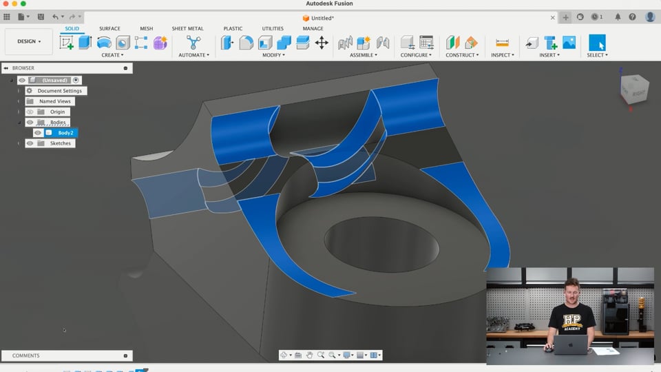
| 05:11 | So, now the next step is probably going to seem a little bit vague so basically what we're going to do is create the profile of the kind of sweep section that the cable tie goes through from a side on view. |
| 05:26 | So, we're going to create another sketch and we can do it on either of these side planes but we'll just do it on this one here. |
| 05:33 | And just to start with what I want to do is project some of the geometry of the part we already have. |
| 05:40 | So, I just hit P on my keyboard, opens the project tab but we can also get to that through here. |
| 05:48 | And then I just want to project the internal hole here and that's just going to bring up the top and bottom edges. |
| 05:56 | And what I'm also going to do is Command P that I've set up in this case brings up the intersect tab, but that's also included under here. |
| 06:05 | So, that's just going to project these same purple lines where the hole in the middle intersects the sketch plane that we're on. |
| 06:15 | So, I'll just click that and do that and then we'll look back at the sketch plane. |
| 06:21 | So, I'm going to start off by making a few construction lines here that are going to help us build the rest of the part. |
| 06:28 | So, I just want to just put a horizontal construction line out here. |
| 06:34 | It doesn't really matter how long and then somewhere off the surface here, build this one up. |
| 06:42 | That's going to be vertical as well. |
| 06:46 | And just to keep things well constrained I'm just going to make that point coincident and then set the dimension from this vertical line to the center of the part to 3.5 millimeters in this case. |
| 07:04 | So, now I'm going to start building up some circles that are kind of going to build out the shape of the part here. |
| 07:11 | So, we'll take the construction mode off and again we're going to do three concentric circles but we're going to start off by making the first one tangent to these two lines that we just drew and we'll make the diameter of that at 20 millimeters. |
| 07:36 | And then again we're going to make one at 16.8 millimeters and another one at 15 millimeters. |
| 07:43 | And these dimensions you might be wondering where I got them from. |
| 07:48 | Just measurements that have been basically taken from the cable tie that we're using to suit the cable tie and fit it, but you'll see as we move forward how this all kind of comes to life and those dimensions will make a little bit more sense. |
| 08:05 | So, again just another construction line down the center there of the circle that we're going to use in just a moment. |
| 08:12 | Now, we're going to start sketching some non-construction lines. |
| 08:16 | The first one is going to just come out to the midpoint on the top of this, the midpoint shown by the little blue triangle there. |
| 08:26 | And then we'll do another one as well and we're just going to set the angle between these two lines to just dimension that at about 8 degrees. |
| 08:39 | Works pretty well. |
| 08:41 | And then a similar thing, come down to this line here. |
| 08:49 | And in this case, doesn't particularly matter but something at about 25 millimeters. |
| 08:58 | And then here this one, we're going to do that same, sorry, 25 degrees. |
| 09:05 | This one here is going to be the same 8 degrees back here. |
| 09:08 | And then I just want to close this profile in like that. |
| 09:16 | So, if we hide that body, we can see we've got this kind of closed profile in here and we're going to be using what we've created with this profile and this shape to make the rest of the part. |
| 09:27 | So, I'll just finish that sketch, show that body again and we'll jump into another extrude here and just select some parts that we're going to work with here. |
| 09:43 | So, we've just selected those profiles and I'm going to set the direction of the extrude feature to symmetric and then I'm going to dimension the whole width of it and set that to 10 millimeters, which matches the outside of our circle boss that we made before. |
| 10:06 | But I'm going to create a new body and then I'm going to join them together soon enough. |
| 10:11 | So, now we have two bodies up here in our browser for our part and we're going to work to cut some more features into this now. |
| 10:20 | So, the first one we're going to do with an extrude and then show the original sketch, which got hidden. |
| 10:27 | So, we're just going to extrude that profile there for that kind of inner circle and the next one as well up through the part to make way for the head of the rivet. |
| 10:40 | But we can see that in this case it's cut through both our bodies and we only want it to cut through the top one here. |
| 10:49 | So, we'll just hit OK for that. |
| 10:53 | And then we're going to move on, next we're going to cut the slot with another extrude, just showing that sketch for the actual zip tie to go through. |
| 11:04 | So, we'll just rotate around so we can see that and the same thing here, we're going to go symmetric because we're working from the center line, dimension the width of it and then we're just going to make a 5 millimeter width to allow our cable tie to slip through that gap there and then hit OK because that's just going to cut through that one body here. |
| 11:31 | And if I hide that sketch, we can see now that we've got the basic kind of form of the part shown there. |
| 11:39 | And now what we're going to do is use the combine tool to combine those two bodies together and just hit OK. |
| 11:46 | And now that just makes it into a single body. |
| 11:51 | So, the next thing that we need to do is we're basically done, but we're just going to add some fillets or radiuses to some of the corners just to kind of soften up the design and make it reduce any stress concentrations while we're at it as well, not that it's really any type of structural part. |
| 12:09 | So, we'll start off with the fillet tool and if we just click each edge that we want to apply a radius to, we can just hold Command while we're doing that to make a selection set and then we're just going to make this half a millimeter in this case to round the inside corners of the kind of passage there for the zip tie and then we're just going to create another selection set here so we can use one feature, one fillet feature for the tool but get quite a few different selection sets for different radiuses in there as well. |
| 12:47 | So, these two edges here, we're going to round those to 15 millimeters just to make a nice big radius there and then finally we're going to add another selection set and then do these ones here that go into the kind of flange for the part and we'll set those at about 1.5 millimeters like that. |
| 13:12 | And sometimes it is good to break up the features so we're going to create another fillet feature with a few more selection sets just so we can break up them into different groups, because if we went from here and tried to add some more selection sets into the part, basically we're applying the radiuses to the edges of the part from the original model, but in some cases we actually want to lock that in and then apply them to the edited model. |
| 13:44 | Hopefully that makes a little bit of sense but we can see here we have that fillet feature in our timeline with a few different selection sets but what we're going to do here is create another fillet feature and now we're going to round the edges of the already modified part. |
| 14:03 | So, the next ones we're going to do are just on the outsides of the tabs here. |
| 14:11 | So, we're just going to select a few edges here, we're going to make those 0.5 millimeters just to kind of soften all those edges, makes the part look a little bit more finished and just takes off any sharp edges basically and then the same thing again, we'll hit ok to lock that in and we'll do the next selections, the next fillet feature on the already modified part. |
| 14:38 | So, here we're just going to put a really small radius on the edges of those parts just to finish it off and there we go, that's the part finished. |
| 14:55 | So, we'll be able to put a rivet in through here and then the cable tie can go through this part here just as we looked at the real part just before. |
| 15:06 | So, with that finished, it's a pretty simple process from here, we can go to Utilities, go to Make and then go to 3D Print, that's going to bring up this little 3D Print tab here. |
| 15:18 | From here we just need to select the, well get the selection that we're going to 3D Print, in this case just a single body here. |
| 15:26 | The format is just the type of mesh file we're using, STL binary is a nice simple one that's perfectly suitable for what we're doing here. |
| 15:37 | The unit type we've modelled in millimetres so we want to keep it in millimetres so it's the same scale. |
| 15:43 | The refinement, because it's a really small part, we'll keep that as high so we keep all the details. |
| 15:48 | And then down the bottom here we can send this directly to our 3D Print utility. |
| 15:53 | So, rather than export it as an STL mesh and then open it in our slicer software which we're going to jump into in just a moment, we can actually do it, send it straight to the slicer from Fusion in this case. |
| 16:08 | So, we're just going to hit ok there. |
| 16:10 | And we can see this has opened Bambu Studio and dropped that part right into the middle of our workspace. |
| 16:17 | We can see how small it is there compared to the build plate. |
| 16:20 | I will just make a note before I get into this side of the software, if you have any questions come up relevant to today's discussion, anything on CAD or 3D printing, feel free to ask in the chat and I'll do my best to answer them at the end. |
| 16:35 | So, here we are in our Bambu Studio slicing software for our Bambu Lab X1E that's just behind me here. |
| 16:44 | And that's just dropped the part straight into the middle of our print bed which is completely fine in this case and it's actually in a good orientation for printing. |
| 16:54 | If it wasn't, we could come over here and we can move it around to different areas, you can see there that it's just sitting in a pretty good orientation. |
| 17:05 | We could choose to lay it on another face like that, but I'm pretty happy with it in that place there. |
| 17:12 | That'll minimise the need for any supports and make sure we get a good result out of the part. |
| 17:18 | And we could also duplicate the part and copy it to lay out a whole bunch of them on the print bed there as well. |
| 17:29 | If we wanted to print say 10 of them at once to use them, or have a little collection of them that we can come back to and use them on our project. |
| 17:40 | But in this case I'm just going to keep things moving quickly, print one of them so it'll print in just a few minutes behind us in just a moment. |
| 17:48 | Over here on the left hand side we're under the prepare tab and we're going to print this with PLA. |
| 17:56 | We've actually got some eSUN PLA, it's just some high speed PLA that we're running through the machine that we can print really fast basically. |
| 18:07 | But this is all just the basic setup of the printer, the type of build plate we have in there, and then these are the main settings down the bottom here. |
| 18:17 | So, we can change these if we needed to to get different results. |
| 18:23 | We're just going to keep things really basic. |
| 18:26 | So, there's going to be 20% infill in the part, so that's basically meaning 20% of the structure of this part is going to be printed plastic and the rest of it is just going to be divided by this kind of structure in the middle that I'll show you in a moment. |
| 18:43 | And we have enable supports on just because we're going to need a little bit of support for this overhang here. |
| 18:51 | If we wanted to we could go into the advanced settings here and you can see all the different speed settings and things like that as well. |
| 18:58 | And all our temperature settings in this case are controlled under the actual filament here. |
| 19:04 | You can see the nozzle temperature and everything here is set to 220, but we don't need to come into that. |
| 19:10 | Keeping things really simple, just running with the default settings here. |
| 19:14 | So, from here it's just a matter of hitting slice plate and we can see that the slice has done its magic and broken the part up into all these different layers here. |
| 19:25 | And we've got this little key on the side showing the different colours and what they correspond to. |
| 19:32 | So, we have the support here shown in green just under the front and then the outer walls of the part, the seams are shown in white and so on. |
| 19:42 | And if we drag this down we can see how the part is kind of built up in those layers and because it's such a small part it's basically all solid. |
| 19:51 | We've got a little bit of this infill shown in the middle here as well. |
| 19:57 | But we'll just keep things simple and move to the next step. |
| 20:01 | And I'm just going to hit print plate but I'm going to jump over to the yellow it's shown here, it's actually more of a cream colour. |
| 20:11 | So, you can see it a little bit easier. |
| 20:14 | And then if I send that to the printer it'll basically get started and we'll be able to see it actually doing its thing in just a moment. |
| 20:23 | And while it's printing I'm just going to move on to show you another feature I've been having a bit of a play around with. |
| 20:29 | In Fusion, that might be useful for a project like this or anything that you might be working on. |
| 20:35 | So, that's just sent that over to our printer and we can see this has jumped us over to the device tab here and these printers actually have the internal camera so we can keep an eye on the print if we're working remotely. |
| 20:52 | I could be working from home and start a print and have this working away in the workshop and check in every now and then with the printer just to see that it's all working out. |
| 21:03 | We can just see the print head moving around there and it's going to do some kind of calibration while it's warming up the print bed and the chamber and then it'll purge any extra filament out of the bottom of it as well. |
| 21:16 | But while that's doing that we'll just jump back over to Fusion and have a look at something a little bit different. |
| 21:24 | So, I'm not 100% sure that this configuration, these tools here are actually included in the free for private use version of Fusion but they are in this paid version that I'm working with. |
| 21:40 | So, basically what these configurations allow us to do is create very similar versions of the same design, say for example this one has been designed using a certain size cable tie and an M4 rivet but maybe we want to use an M5 rivet or something like that. |
| 22:01 | So, I'll just show you how to create, or quickly create another version of this part with those different dimensions without actually just saving it as another file, it can all be captured inside one design file here. |
| 22:16 | So, what we're going to do is just open this configuration table. |
| 22:22 | And we'll just rearrange things a little bit so we can see what's going on. |
| 22:28 | So, this just shows that we have a single configuration in the workspace because we've only been working with one design so far, but we're going to go through and select a few of the dimensions we want to change and then we'll create another configuration as well. |
| 22:43 | While we're at it I'm just going to rename this first one as M4 and then I'm going to jump over here and add aspects. |
| 22:51 | It's just giving me a little note here about what it is we're doing but obviously I'm going to talk you through that so we can just ignore that by now. |
| 22:59 | So, everything that's highlighted in blue here contains these parameters that we can use for working with different configurations. |
| 23:09 | So, if we click the first sketch here we can see that it comes up with the different diameter dimensions that we can use and modify. |
| 23:20 | So, if we just hover over these you can see in the workspace here they're bringing up, just highlighting each of the ones so we can see what we're working with. |
| 23:29 | We are going to include all three of those in our configuration and we'll just hit ok there. |
| 23:36 | So, that's brought those three up into the workspace here as well. |
| 23:40 | We're going to go through and choose a few more dimensions as well. |
| 23:45 | So, the next one, this extrude feature, we don't need to change anything about that, we'll keep the boss thickness at 4mm in that case. |
| 23:55 | But this next sketch here we're going to use some of the dimensions on that as well. |
| 24:01 | So, we've got that one linear dimension here, that was 3.5, we're going to include that. |
| 24:07 | And then we're also going to include the diameter dimensions here as well. |
| 24:16 | I think I need all of them. |
| 24:19 | Ok. |
| 24:23 | And then we also need, sorry I just jumped out of that, to include the width of that part, so the distance for that extrude as well. |
| 24:35 | So, let's have a look at, I'll drag this out a bit and create another configuration and change a few of these. |
| 24:45 | I'm just trying to keep this part on the side here so you can see as we change things, the changes it makes. |
| 24:51 | So, we're just going to add one configuration in here and then we're going to name that M5. |
| 24:59 | So, that internal diameter here, we're going to make that 5.5 for our M5 rivet. |
| 25:06 | And then we're going to also increase these dimensions a bit to allow the head of the rivet and we can see that this is kind of boring out the part here. |
| 25:16 | We're going to make this last one here 12 on the outside. |
| 25:21 | And the width of the part while we're at it of the next extrude, we're going to make 12mm as well, so that comes out to match it. |
| 25:30 | So, let's have a little look at some of the other changes we can make. |
| 25:36 | That 20mm one I actually want to keep the same. |
| 25:41 | One moment, let me just check my notes. |
| 25:46 | Which I don't have anymore, that's all good. |
| 25:51 | So, let's have a look at changing some of these other diameters here, 3.5mm. |
| 25:59 | So, we're going to make that 3.5 into a 4.5 just to offset the slot there a little bit more and we want to move some of these radiuses out a little bit as well. |
| 26:17 | Maybe not quite so much that much. |
| 26:20 | This one here. |
| 26:28 | Make this one 14 and then we'll pull this one here out to 15.8 and we can just see how that's kind of adjusted the part there as well and that's just the printer calibrating behind us and it's starting to print now. |
| 26:50 | But anyway, we can see now that we've just updated this model and changed the size of the hole here and then also some of the other dimensions in it just so it's more suitable for an M5 rivnut and we can still get the zip tie through this gap here past the kind of new boss that we've created. |
| 27:12 | So, what we can do from here is we can just flick back between the two. |
| 27:19 | If I zoom in a bit you see how they can change or if I just close that we can see now in the browser we have these two different configurations for the part and we've just basically adjusted the size. |
| 27:31 | See we've got a little bit of an error here. |
| 27:34 | Should be able to fix that. |
| 27:37 | So, we've just created these two different configurations for the same design for the part, but just for two different size pieces of hardware there. |
| 27:45 | So, a pretty simple way to do things and if you're working on something where you're creating, I don't know, a series of parts under the same design, but they have slight differences in them, using that configuration table is a good way to do that and save yourself some time and obviously you can create 20 different configurations for something all within one design file there rather than using up all that space on your computer or getting confused about, which version you're working with. |
| 28:19 | It just keeps things a little bit more simple for file management and it's a bit more efficient as well. |
| 28:24 | So, with that covered while this is finishing off we'll just have a look back at that here and we can see it's just starting to lay down those first layers now and we've got about three minutes remaining. |
| 28:35 | So, basically what it's been doing up to this point is just laying down these calibration lines, warming up the nozzle and the platform. |
| 28:50 | Not sure what it's doing now. |
| 28:54 | Looks like it's just cleaning the nozzle because it saw a bit of stringing. |
| 29:04 | Just want to keep my eye on it for just a moment. |
| 29:22 | All right, we're away again. |
| 29:32 | Yeah, ok, cool. |
| 29:34 | So, two minutes or so to go there and that should be done in just a moment. |
| 29:38 | Just going to jump over to my notes and just see if we've got any questions I can get to before I pull that out of the printer. |
| 29:54 | All right, Joe, "When you're modelling something to 3D print do you have to model anything differently compared to when you're going to get a part machined?". |
| 30:02 | Yeah definitely, you always want to keep in mind design for manufacturing. |
| 30:06 | So, that's designing around the limitations of the manufacturing process we're using, but also designing to its advantages as well. |
| 30:15 | So, let's think of an example of this, if you're designing something to be metal 3D printed, you don't have to worry about minimum tool sizes that you're working with with CNC milling for example and you can hollow out the inside of the part, as long as you allow for a hole in the part where you can drain the material out of it that wasn't printed or fused together. |
| 30:45 | But there are other considerations that you need to think about around the manufacturing method and that might just come down to the fact that a 3D printed metal part isn't generally going to be as strong for the same design as a CNC machined part, so maybe you have to change the structure a little bit to account for that. |
| 31:05 | But that is definitely something that you want to keep in mind, you don't want to be 3D printing a part that was designed to be CNC machined unless you're doing it of course as a prototype. |
| 31:18 | But for end use functional parts you want to keep in mind the limitations of the manufacturing process. |
| 31:26 | Some examples for 3D printing, I actually have a bit of a file on my computer here I can bring up in just a moment. |
| 31:36 | So, it has some design rules here from ProtoLabs and these give you an idea of the different types of 3D printing down the side here and some constraints that you need to work around for 3D printing. |
| 31:49 | For example, let's have a look at the holes, like a minimum hole size here for an FDM printer like this, they're recommending 2mm, so that's something you have to keep in mind when you're working through the part, not to use a hole smaller than that for example and obviously every printer is different. |
| 32:10 | But yeah there's a whole lot of rules here that can be applied to the different types of 3D printing and the same goes for any type of manufacturing process as well. |
| 32:22 | Alright, looks like we've just finished that so before I come back to some questions, I'll just get that out of the printer. |
| 32:38 | Jump under the overhead here so we can see a little bit of support under that overhang, just easy, just break that off and then there we have the printed part just like that and if I pull the cable tie out of this, we can slide that cable tie through and there we have it. |
| 32:59 | 3D printed part, we can rivet that into any sheet metal for a body panel, something like that and then use that to route some lines through the vehicle and tie up the cable tie like that. |
| 33:14 | So, I'll just jump back over to those questions. |
| 33:21 | Brute force and ignorance, "What materials, FDM, do you recommend for functional parts in the engine compartment? I'm concerned about heat cycling, exposure to solvents and vibrations.". |
| 33:33 | So, we're actually working on a 3D printing course at the moment that covers a lot in depth of all of those materials so keep your eye out for that in the future. |
| 33:43 | I actually have another document here, I'll just open up, filament guide from Bambu Lab for their materials that we work with something like this and I'd recommend going and having a look at this document. |
| 33:58 | So, along the top here it has all of these different materials so PLA, which is what we just used, PETG, ABS, ASA, polycarbonate, TPU, which is like a thermoplastic elastomer, like a rubbery material and then we have some similar materials here all reinforced with carbon fibre as well. |
| 34:19 | And that's probably the direction that I'd start to point you if you're looking at doing FDM for engine bay components here. |
| 34:27 | So, we can see here we have the heat resistance, so that's more accurately the heat deflection temperature at that stress. |
| 34:38 | And we can see here how something like PLA that we just printed with has 57 degrees heat deflection temperature, but if we move up to something like PTCF then we're all the way up at 200 degrees. |
| 34:55 | So, that depends on the vehicle that you're working on, if it's forced induction or something like that. |
| 35:01 | But something like that material would likely withstand the abuse of a motorsport engine bay quite well given it wasn't bolted right to a heat source or something like that whereas something like PLA wouldn't be the case. |
| 35:15 | I think for the kind of cheaper, more accessible end of the spectrum, I would definitely recommend having a look at ASA for something like what I'm talking about. |
| 35:26 | But then the carbon fibre reinforced ones are also some good options as well. |
| 35:31 | Some of them also have, it's not showing so much on here but some of them are better for chemical resistance as well, I just can't think too much off the top of my head exactly what that is. |
| 35:48 | Nylon, which is not shown on here, oh yeah it is, PA6 so that's nylon, polyamide 6 in this case, this one's carbon fibre reinforced. |
| 36:01 | Nylons are really great 3D printable material and as you know the intake manifolds used on many modern vehicles are made from injection moulded nylon, but the properties of a 3D printed part is very similar as well and it's really well suited to engine bay use. |
| 36:18 | Can be used for intake manifolds and things like that on naturally aspirated builds, even potentially on some forced induction builds as well. |
| 36:27 | So, check out nylon if you really want the best FDM 3D printed material, but I'd also recommend having a look at, if you're going to get something made by a third party manufacturer over a service like Craft Cloud or something like that, have a look at the SLS 3D printing process. |
| 36:47 | It's not actually SLS in the case of nylon, it's more usually MJF, so that's multi jet fusion and it's a little bit of a different process used to 3D print, but the material's very similar being nylon and that can create some really good parts. |
| 37:04 | Like I showed earlier, the velocity stacks on my 240Z, one that I've got on there at the moment is actually a 3D printed nylon part and that should hold up really well, that's used often on those parts. |
| 37:17 | So, yeah, check out nylon or PA6, PA12, PA66. |
| 37:22 | Just jump back to my notes. |
| 37:25 | So, same, brute force and ignorance, "Is HPA developing a mechanism to share parts as you and HPA members develop printed parts in CAD?". |
| 37:48 | So, we actually have a, I think Jordi's done a bit of answering this already, but we have a CAD forum set up and we have a forum on there where some members are sharing parts as well. |
| 38:02 | So, if we can find the link to that quickly, I'll get you to jump on there and yeah, have a look and if you want to share parts, that's greatly appreciated. |
| 38:12 | But yeah and if you see any parts that we're developing or showing in these webinars and you want to get a hold of the actual file, ask me through the forum, as well and I'll do my best to share what I can. |
| 38:24 | But yeah, that looks like all of the questions so hopefully that's given you a little bit of an insight into how quickly we can model and print Suttoning. |
| 38:35 | That's just a usable part that solves a small issue when we're making a car and obviously we can print larger parts, they're just going to take a little bit longer, the actual modelling process might even be easier than Suttoning like that so it's pretty quick turnaround for something like that. |
| 38:53 | If you're working on a new project and you need something 3D printed as a prototype or an induced part, you can usually knock it out in a morning or something like that, modelling the part to solve whatever problem you need to do and then printing it out at the same time. |
| 39:09 | Most prints that we work on or something like this, maybe print in a couple of hours for kind of bigger parts and then the really big stuff maybe goes up to something like 10 hours or so. |
| 39:22 | So, you get it going overnight, come in in the morning and then you have your part finished and ready to use the next day. |
| 39:29 | So, yeah, hopefully that's given you a bit of insight into that. |
| 39:32 | And we'll be back next week with another webinar. |
| 39:36 | So, thanks for joining us today. |
0:00 - Introduction
3:33 - Beginning the modelling process
10:06 - Adding more features to the cable tie body
11:51 - Finalising and detailing the design
15:06 - Print export to Bambu Studio
16:35 - Bambu Studio print setup & settings
20:23 - Printing + remote camera observation
21:40 - Create variations of same parts quickly in Fusion
29:38 - Q&A