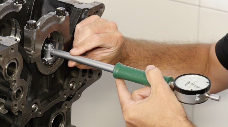
A Bore Gauge, or Dial Bore Gauge as it may also be referred to, is used to accurately measure inside diameters. As its name implies, it's often used to measure the bore diameter of an engine block. This isn't its only use though, and essentially it can be used to measure the inside diameter of many critical engine components.

For example a bore gauge can also be used to check and confirm bearing clearances for both the main bearings and big end bearings of the engine by measuring the inside diameter of the con rod big end journal with the bearing shells installed, or alternatively, the main bearing tunnel in the block with the main bearing shells installed.

The bore gauge that we have here as our example is a metric bore gauge that is suitable for measuring bore diameters between 50 millimetres and 160 millimetres via a dial indicator and is able to measure down to one hundredth of a millimetre or 0.01 mm. Bore gauges are also available in imperial measurements for those more familiar with working in inches. The dial indicator doesn't specifically measure the component we're interested in however, and instead we use it to compare two measurements where the dial gauge shows us the difference.

To do this we first need to zero the dial gauge using a micrometer. Once we've done this, we can the use the bore gauge to check the specific clearance we're interested in. If for example we zeroed the Dial Bore Gauge with the micrometer set to exactly 50.00 mm and the bearing we're measuring showed a measurement of + 0.10 mm on the dial gauge, this would mean the bearing diameter is 0.10 mm or ten hundredths of a millimeter larger than our measurement, or in other words, we have 10 hundredths of a millimeter clearance.
At the end of the bore gauge, we have the head which is the part we fit into the cylinder or whatever it is that we're measuring. The head includes an extension that we can change to suit the diameter we're interested in measuring. In this example we're measuring an 86 millimetre bore and I've got the correct adapter fitted to suit that bore diameter.

The adapters we're using include a teflon button at the end which helps prevent scratching or marking of the cylinder walls when we're actually using the bore gauge.

If we move to the other side of the head, we can see we have a small measuring plunger and this is what's actually going to do the measuring. When we move the plunger in and out, the dial indicator will also move. There are also two small wheels here which will run on the surface of the bearing journal or cylinder wall and this locates and centralises the bore gauge.
Looking to buy a bore gauge? Check out the HPA forum to find the best engine-building tool supplier for you.
Do you want to learn how to use the bore gauge correctly? Dive on into our Engine Building Fundamentals course for further instructions on this and many other essential tools of the trade, or alternatively you can get started with our next free LIVE engine building webinar.


