Dr Ben Diggles. (Originally published Mar 2020).
Until recently, there has been scant reliable public information on the phenomenon of preignition in the boosted 4-valve combustion chamber. However, recent trends towards downsizing of the internal combustion engine (ICE) from OEM engine manufacturers developing highly boosted small capacity direct injection engines, together with the increasing reliance on alternative fuels, particularly alcohol fuels such as ethanol (E85, E100), has shed some light on the subject. Fortunately for tuners, this information has now become available in various technical papers from automotive engineers working for places like GM.
In this article: Alcohol Based Fuels | The Danger Of Preignition | What Causes Preignition? | Preignition & Alcohol Based Fuel | Preventing Preignition | Squish Pads vs Preignition | Slant vs Horizontal Squish | What is Barrel Swirl And Why Does It Matter? | Conclusion
Only the big OEM manufacturers have sufficient resources to study random combustion problems like preignition, but fortunately for us, it turns out their discoveries are directly applicable to other ICE applications of interest to today's tuners, such as import racing with high boost turbos and methanol (M100) fuel.
Alcohol Based Fuels
OEM engineers discovered when running small (usually <2 litres) engines at high (for an OEM application) boost (15-20 psi) and low rpm (2000-3000 rpm) in their engine development programs, there was a random preignition phenomenon previously only seen in racing engines. Preignition is not to be confused with detonation, as the latter is a combustion abnormality that occurs after normal ignition is initiated by the sparkplug. In contrast, preignition is a form of uncontrolled ignition of the fuel/air charge that occurs before the sparkplug is conventionally ignited by the ignition system. While alcohol fuels are recognized as exhibiting relatively high knock resistance compared to gasoline, it is a fact that they are more prone to preignition, which may have something to do with their mono-molecular makeup. Gasoline is made up of complex mixtures of long-chain hydrocarbons. Each different hydrocarbon fraction, when ignited, tends to burn at a different rate, which is why oil companies change their formulations to tailor their fuels for different uses. In contrast, alcohol fuels are simple mono mixtures of relatively short-chain molecules like CH3OH (methanol) or (C2H5OH) ethanol. When these burn, all the molecules in the combustion chamber burn the same way. This is why the onset of abnormal combustion on alcohol fuels is so abrupt. The engine can be making great power right up to the “very edge”, but if you go over the edge, the onset of abnormal combustion is rapid and severe as the abnormally combusted fuel/air mix tends to detonate “all at once”.
The Dangers Of Preignition
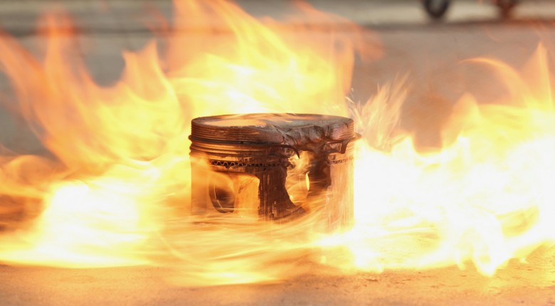
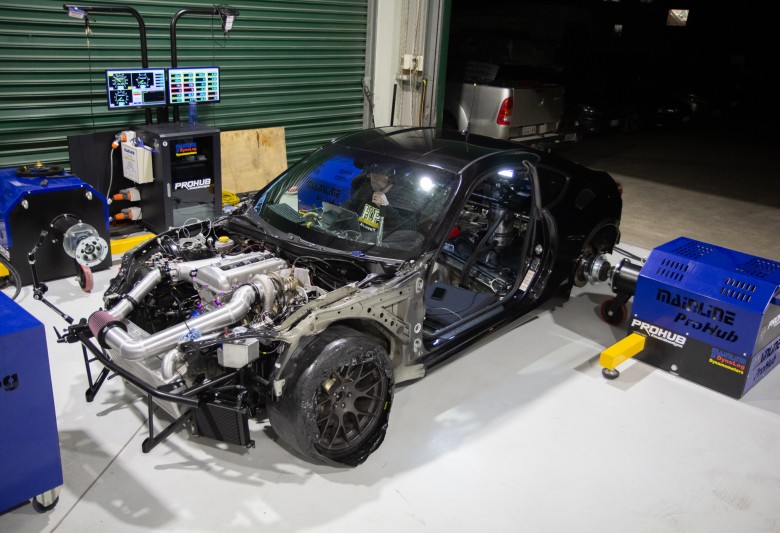
Speaking of abnormal combustion, detonation is child's play in comparison with preignition. We have run our 2 litre, 1000 hp Nissan FJ20ET 4 cylinder dragster into mild detonation several times during its high 6-second and low 7-second passes, and the data thus generated shows the engine, while not happy, would tolerate the high cylinder pressures for some time (at least 6 seconds at a stretch) even at 50-60 psi gauge boost pressure before damage to the engine structure occurs. In contrast, when runaway preignition occurs under the same conditions, and the throttle is not lifted to reduce engine load, the engine’s lifespan is measured not in seconds but in engine cycles. At 9000 rpm, it doesn’t take long (by our calculations, around 100 engine cycles, or about one second) for the preignition to do its ultimate job of blowing the piston crown away, after which the next step in the process is the engines attempt to blow the sump off due to ingress of combustion pressure into the crankcase. This makes lifting the head and pressurizing the cooling system seem somewhat tame in comparison. While it is fair to say our experiences with the 1980s-designed (pre-emissions) FJ20 platform are exaggerated compared to the usual situation found in the majority of modern engines, there’s nothing like an exaggeration of an effect to point you towards examining a problem in more detail to ascertain the cause.
Video: Mark Skaifes first race car, a S12 Nissan Gazelle with an FJ20DE built by author Ben Diggles in action around Mount Panorama Circuit, Bathurst.
What Causes Preignition?
To learn more about preignition, today we need look no further than some excellent investigations of the subject, such as Dahnz and Spicher (2010) and Zadeh et al. (2011)). Dahnz and Spicher (2010) hit the nail on the head when they say “ Currently, the allowable load in downsizing engines is limited by pre-ignition. The damaging effect of preignition is not due to the primary auto-ignition itself but to the resulting extreme knock later in the course of combustion”. But instead of just complaining about something that is holding up an engine development program, OEM manufacturers study the problem and develop solutions. This was shown by Zadeh et al. (2011) who exhaustively investigated the onset of preignition for GM using a 2 litre Ecotec direct injection turbo engine. They used state of the art in-cylinder photography and analysis methods to examine why random preignition occurs in this engine under the following conditions: 2000 rpm, lambda 1.1, and at a relatively high 325 psi Brake Mean Effective Pressure (BMEP) (specific power 97 kw/L), with high speed computers used to log in-cylinder images, cylinder pressure, heat release and many other data for every engine cycle. Because even under these full load conditions the preignition was stochastic (random), in that it only occurred sporadically once every 15,000-30,000 engine cycles on average. So, to avoid being swamped in data, their computers were programmed to firstly recognize preignition events by excess cylinder pressure traces, then they stored only data from the last normal engine cycle prior to the first preignition event, and then for the next 25 engine cycles afterwards.

By doing this and altering variables such as boost pressure, fuelling, engine temperature, spark plug type and orientation, lubricating oil type and piston crown and piston ring configurations, they not only described preignition, but went a long way towards working out the main factors responsible for it. In a nutshell, the results were as follows:
Pre ignition was mainly due to factors that reduced the autoignition flash point of the fuel used, such that it could be auto ignited at comparatively low temperatures by hot surfaces inside the combustion chamber (usually the spark plug). The main factor reducing the autoignition capability of the fuel was oil dilution. Factors that acted directly to increase preignition included wetting of cylinder walls by direct injectors, lower cylinder wall temperatures, and preignition events in previous engine cycles. Indirect factors effecting pre ignition included higher end of compression gas temperatures as a result of increased compression ratio, leaner fuel mixtures, higher engine loads, or previous preignition events. More to the point, several factors that reduce the preignition frequency were identified. These included targeting injectors and increasing port tumble and in cylinder mixing (i.e. better mixture preparation) to reduce fuel wetting of the cylinder walls, optimising fuel mixtures and oil formulation (use of oil with low sulphated ash, low calcium and low Noack Number), reducing oil intrusion into the combustion chamber by increasing oil ring tension, and reducing spark plug temperature by using cooler plugs and indexing spark plugs with the ground electrode towards the intake valves.
Why Is Preignition Worse With Alcohol Based Fuel?
The findings of Zadeh et al. (2011) that preignition is due mainly to reduced autoignition capability of the fuel by oil dilution fits in well with an explanation of why alcohol fuels tend to be more susceptible to preignition in high boost engines. The preignition point of alcohol fuels by themselves may be, on paper slightly higher that that of gasoline (typically 470 vs 400 °C), but the autoignition point of alcohol fuels is likely to be degraded more readily by oil contamination than that of gasoline, possibly due to the relatively low molecular weight (i.e. small size) of the alcohol fuel molecules. A little bit of oil makes a big difference to alcohol fuels. Also, because the stoichiometric air/fuel ratio for alcohol fuels (6.4:1 for methanol, 9.1:1 for ethanol) are so much richer than for gasoline (typically 14.7:1), there is a lot more fuel in the combustion chamber, particularly if richer mixtures are used at high boost, which means the chances of cylinder wall wetting, and therefore mixing of oil with the fuel, are much higher. When you factor in the fact that IC engines running alcohol fuels tend to be operated at higher cylinder pressures (after all, why are you using alky in the first place?), this all adds up to explain the issues seen by racers with alcohols and preignition.
How Can We Prevent Preignition?
What else can we do to stave off preignition? Well, anything you can do to increase fuel vaporisation prior to the fuel air mix entering the cylinder will help. This means looking at injector aiming and positioning, injector sizing and fuel pressure, and getting the engine to the optimum running temperature (the “Goldilocks Zone” - not too cold, not too hot). Zadeh et al. (2011) found that optimising the temperature of the engine structure definitely helps; if the cylinders were too cold, the risks of preignition were increased. Critical temperatures for vaporizing alcohol fuels at atmospheric pressure are in the vicinity of 65°C (methanol) to 78°C (ethanol). This means you should get your coolant temperature over 65°C to help the cylinder walls vaporize any liquid fuel that makes it into the cylinder. Once in the cylinder, appropriate port and combustion chamber shapes can also help with further mixture preparation through processes such as tumble. Modern inlet port and combustion chamber designs are now pretty much optimized for emissions purposes, and an efficient burn means not only no wasted fuel, but the chances of preignition are also further decreased. Similarly with the intake air temp, if you get too much below ambient air temperature (like when using a dry ice intercooler or a big shot of nitrous), you will risk running into problems vaporizing all the fuel, and the risks of liquid fuel entering the chamber increase. This is why alcohol fuels and forced induction are to some extent a match made in heaven. The excess intake heat from the adiabatic compression of supercharging can be mostly taken out by the high latent heat of vaporization of the alcohol fuels, without necessarily requiring intercooling, provided that the alcohol is introduced far enough upstream to allow it time to vaporize. The latent heat of vaporization of fuels like methanol and ethanol are, relative to gasoline, enormous. Why not use this to your advantage if you can?
Mazworx SR20VE CNC machine work elimination squish areas.
Squish Pads vs Preignition
Once our fuel/air mix is inside the cylinder, combustion chamber and piston top designs that promote movement of the fuel/air mixture towards the spark plug rather than towards the cylinder walls will not only improve performance, they will also help stave off preignition. In some engines, especially those designed for road use that are converted for high boost and rpm racing use, depending on the combustion chamber design this may mean reducing or even eliminating squish pads. OEMs build squish into engines to enliven mixture preparation at relatively light loads (e.g. low specific outputs typical of road cars), but this does not mean the same design is appropriate under heavy load, and/or high rpm with boost, as all of these conditions naturally increase mixture motion. Indeed, excessive mixture motion when an engines’ operating conditions are changed well beyond their manufacturers intended use (e.g. we want 40-60 psi boost (or more!) at 9000 rpm instead of 7 psi boost at 6000 rpm), especially if the piston crown has been altered (e.g. to increase compression ratio), can lead to such things as excessive squish-to-bore ratios, and excessive mean squish velocities, potentially resulting in excess mixture motion and harsh/irregular combustion. The latter can easily lead to abnormal combustion under the new operating conditions, especially a high cylinder pressures in import drag racing such as whenever the BMEP exceeds 700- 800 psi (around 8-10 hp/ hp/in3). Indeed, when you look at how manufacturers such as Nissan have modified the SR20 engine for high output (by comparing the SR20VE combustion chamber with a normal SR20 combustion chamber), it is easy to see that they have indeed reduced the squish to bore ratio on the engine with the higher specific output (Figures 1,2). When adding 2 to 4 (or 6 to 8?) bar gauge boost pressure to these same SR20VE engines, some tuners have found it beneficial to eliminate the small squish areas completely as demonstrated by Mazworx CNC work in the video above.
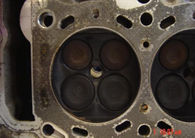
Figure 1. Combustion chamber of SR20VE (above) rated at 152 kw naturally aspirated (76 kw/L). Note reduced squish pads compared to Figure 2 (below) which is combustion chamber from a SR20DE rated at around 115 kw (57.5 kw/L) or approx 32% less specific output than the SR20VE. Nissan engineers decreased the squish to bore ratio when they increased the specific output. Now what happens if you add another 30-60 psi of boost?
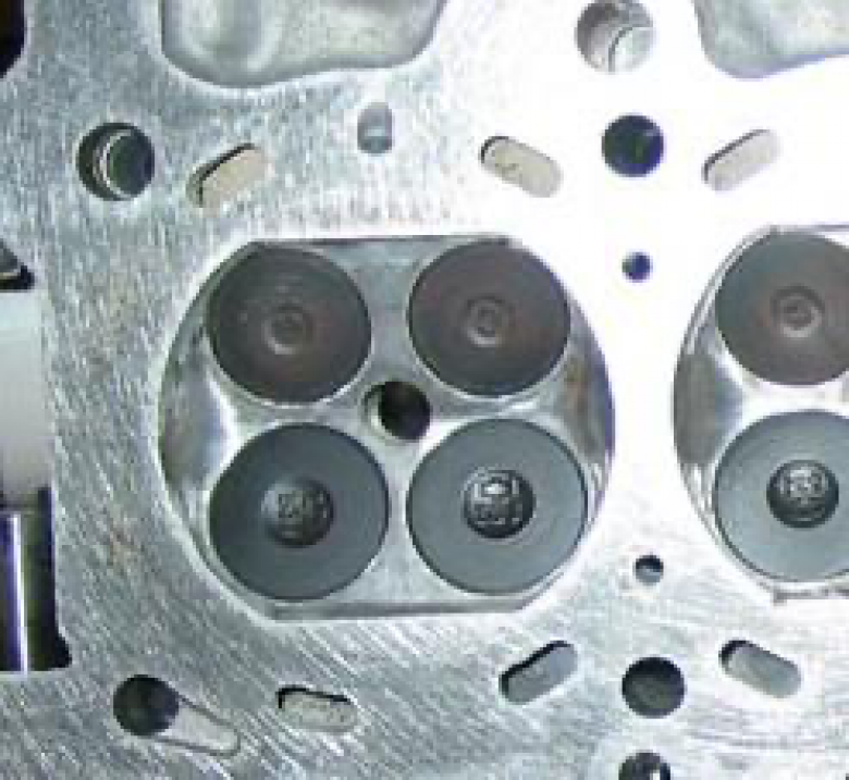
Figure 2 SR20DE as referenced above.
Slant vs Horizontal Squish
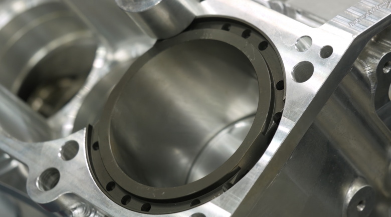
With outputs exceeding 1400 hp from 2.2 litres (134 cubic inches, meaning well over 10 hp/in3, or 1050 kw from 2.2 L = 478 kw/L) during its early factory racing development (GM Racing 2002), the GM Ecotec port fuel injected inline 4 cylinder modified for high RPM and high boost drag racing by factory GM engineers in the early 2000’s was (and still is) amongst the most impressive OEM forced induction engines in recent times. Besides desirable features for in-cylinder mixture preparation like high tumble ports and a rocker (to multiply valve velocity and lift), a quick look at the Ecotec combustion chamber modified for drag racing (Figure 3) reveals that when combined with a flat top piston, the combustion chamber would generate a form of “slant squish” (as promoted by Mitsubishi - see Miyamoto et al. 2006) or “taper squish” (from Toyota, see Adachi et al. 1998), that would tend to promote movement of fuel mixture towards the spark plug as the piston rises to TDC, and away from the crevice volume/top ring land area. A similar effect can be achieved with the SR20VE engine, but only by machining the squish areas away. When you are chasing the very last HP in a high boost, high RPM engine, this concept of slant squish over horizontal squish is worthy of more than a cursory examination, for the following reasons....
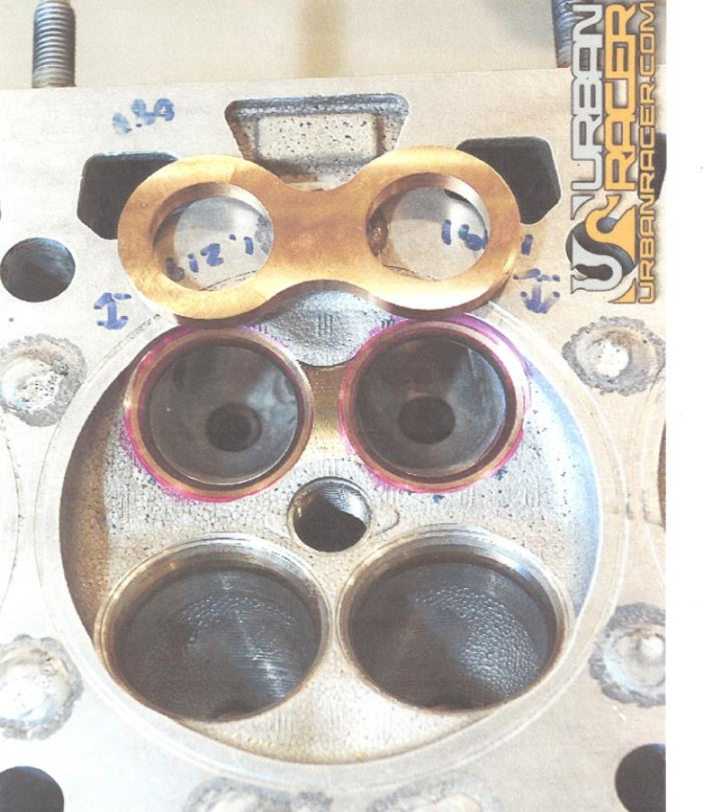
Figure 3. Combustion chamber of the GM Ecotec, as adapted to high boost drag racing. Features include no horizontal squish, dry deck and a one piece exhaust valve seat designed to maintain exhaust seat integrity at very high specific power levels.
When horizontal squish is used in a high boost 4 valve engine, besides increased combustion harshness at high specific outputs, in some engine designs piston rock (forged pistons with large piston to bore clearances are necessary in this environment) may lead to the horizontal squish tending to “reverse flow” as the piston rises towards TDC, sending any unvaporised fuel towards the crevice volume. This would be more problematic with engines having the inlet valves on the left side of the engine when looking from the front with clockwise crank rotation (examples include Nissans FJ20 and SR20), rather than those with the inlet valves on the right (GM Ecotec, Honda K20/24) (see Fig 4). Interestingly, the fantastic K series Honda motor also loves forced induction, is this why Honda chose clockwise rotation with the inlet valves on the right?
Fuel in the crevice volume cannot burn as it is quenched by the cylinder wall and largely shielded from the combustion flame front (especially in a squish area). However, while hidden away down there it can cause all sorts of mischief by mixing with the oil film on the cylinder wall, especially if the engine is tired and leakage by the rings is increasing, or if the cylinder bores are out of round (which can be due to wear and tear or even excessive combustion pressures when high boost pressures are used). This fuel-oil mix is potentially a precursor to preignition, all that is needed is for the fuel-oil mix to get near a hot spot, with the sparkplug being the prime culprit. But how does the fuel-oil mix get from the crevice volume to the sparkplug?
What is Barrel Swirl And Why Does It Matter?
A study of the induction path in a 4 valve pent roof combustion chamber shows that it follows a “barrel swirl” inherent in the design (Fig 5).
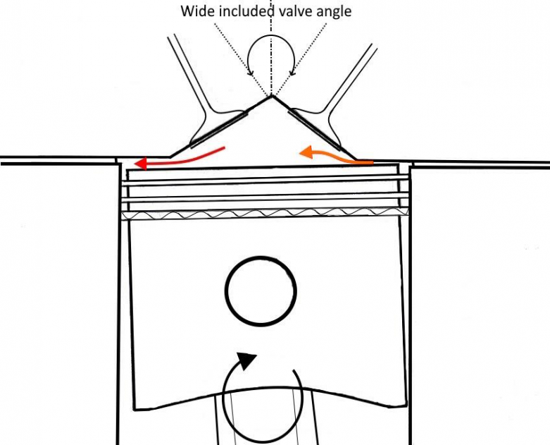
Figure 4. “Reverse squish” in an engine with horizontal squish bands and a wide included valve angle. Assuming clockwise rotation and piston rock (exaggerated in the diagram), engines with the inlet on the left hand side of the diagram would suffer from reverse squish into the crevice volume (red arrow), while engines with the inlet valve on the right side would have squish moving mixture towards the spark plug (orange arrow).
During induction of the fuel-air charge in a 4 valve engine, the barrel swirl begins as the piston descends after the inlet valve opens. The charge gains momentum then as the inlet valve closes as the piston moves back up for the combustion stroke, the reduction in cylinder volume promotes even more swirl in ever tightening circles until it breaks into random squish turbulence just near TDC. Because of the direction of the barrel swirl, fuel- oil mixture trapped in the crevice volume under the inlet valve will eventually be pushed across the spark plug as the piston rises. If preignition occurs at an early stage in the induction cycle, the barrel swirl takes the resulting flame front into the cylinder such that the last part of the flame path is directly under the inlet valves. Because heat release during preignition occurs much faster than during normal combustion (Zahdeh et al. 2011), this is why in 4 valve engines the holed piston phenomena (the inevitable result of runaway preignition) occurs on the inlet side of the piston, rather than right in the middle of the piston as tends to occur in 2 valve designs.
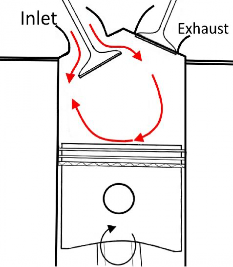
Figure 5. Cross section of a pent roof 4 valve cylinder showing direction of barrel swirl. The fuel/air mixture moves past the inlet valve (on the left in this design) as the piston descends on the induction stroke. The mixture path of the barrel swirl is shown by the red arrows.
Instinct would suggest that the inlet side of the piston should be the coldest and that it would melt on the exhaust side instead, but in 4 valve engines it is barrel swirl that causes it to melt on the inlet side of the piston as the inlet side is right at the end of the flame path, so receives the most heat. This is why people like Brian Hart in the 1980’s Formula 1 era resorted to adding a second spark plug in the cylinder block up near the head, directly under the inlet valves. Hart could do this because his engines were made without a head gasket with the head integral to the block. As an aside, with really bad preignition you can trace the direction of the barrel swirl (and hence flame path) by the damage it causes – sometimes the exhaust side of the cylinder head is melted first before the piston melts through on the inlet side (the damage follows the direction of the barrel swirl).
While instinct may lean towards reducing piston top ring crevice volume with the theory that it would reduce the amount of fuel being trapped in this dead space, the work of Zahdeh et al. (2011) suggests otherwise. Their work suggested that reducing the crevice volume actually increased the chances of the fuel oil mixture being released from the crevice, in which case the barrel swirl will eventually take it across the spark plug. It seems that the best way to reduce the likelihood of preignition is to reduce wherever possible the incursion of oil into the chamber and the impingement of fuel onto the cylinder walls (Figure 6).
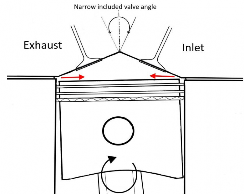
Figure 6. An ideal high boost 4 valve combustion chamber for methanol fuel. This has the inlet valve on the right side of the cylinder head (when looking from the front) and a combustion chamber design which utilizes slant squish to prevent reverse squish flow and reduce combustion harshness at BMEPs exceeding 800 psi.
Conclusion
It is notable that the most effective high boost 4 cylinder engine for drag racing over the past 20 years has been the GM Ecotec 2.2 L platform. This engine in the hands of Carl Brunet from Canada, was the first 4 cylinder engine to run into the 5 second zone (5.95 at 230 mph, in March 2020). This is a phenomenal feat likely requiring over 2200 whp from 2.2 litres displacement (>16.5 hp/in3, with a BMEP likely exceeding 1500 psi). The GM Ecotec has clockwise crank rotation and the inlet valves are on the right of the cylinder head (when looking from the front). The cylinder head/combustion system of the Ecotec is clearly providing very stable combustion and control over preignition despite extremely high boost and large piston rock that is sometimes present (at 800 kw/L specific output, piston to bore clearances are usually at least 0.007 inches, so there must be some rock).
Both the GM Ecotec and the Honda K20/24 have both a favourable slant squish combustion chamber design as well as inlet valves on the right to help direct flow of inlet mixture towards the spark plug when piston rock occurs. In contrast the Nissan SR20 (and FJ20) have squish bands and the inlet valve on the left, with piston rock trapping residual fuel in the squish area and angling it towards the crevice volume, where it can cause trouble. Is this part of what gives the GM Ecotec (and more recently the Honda K series) the edge over other 4 cylinders in import drag racing? By inherent design, do these amazing modern 4 valve engines have the complete combination of characteristics that reduce the chance of preignition when adapted to extreme boost levels on methanol fuels?
References
Adachi S, et al. (1998). Development of Toyota 1ZZ-FE Engine. SAE Technical Paper Series 981087.
Dahnz C, Spicher U (2010). Irregular combustion in supercharged spark ignition engines - pre-ignition and other phenomena. International Journal of Engine Research 2010 11: 485- 498.
GM racing (2002). GM Ecotec engine handbook. General Motors Corp. 22 pgs.
Miyamoto et al. (2006). Enhancement of combustion by means of squish pistons Mitsubishi Motors Technical Review 18: 32-41.
Zahdeh A, et al. (2011). Fundamental Approach to Investigate Pre-Ignition in Boosted SI Engines. SAE paper 2011-01-0340.
