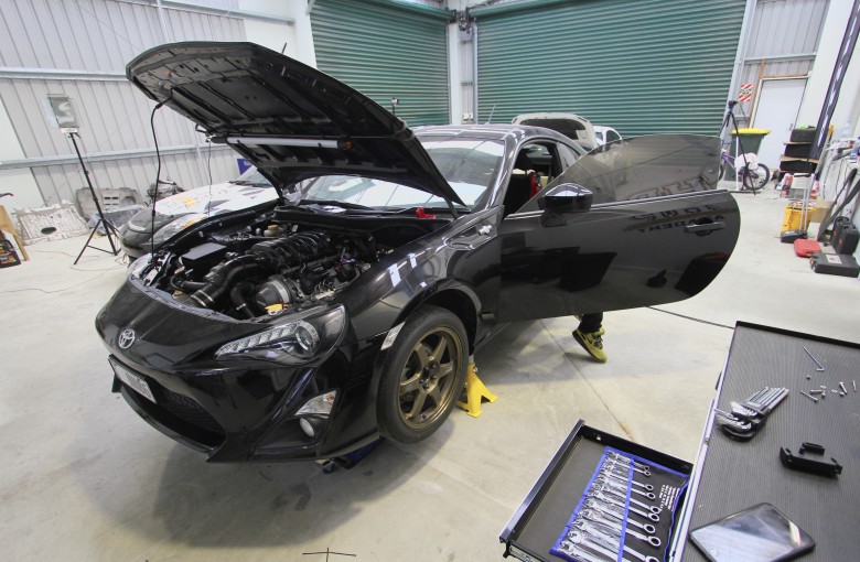
Planning is a key element to any successful project, automotive or otherwise yet it’s so often ignored and the outcome unsurprisingly shows it. Welcome to the second instalment (See Part 1) of our Project Panhard build where we are detailing the planning, wiring, configuration and tuning of a Toyota 86 that’s had a 1UZFE V8 fitted in place of the stock FA20. In this article I'll take you through the planning stage and you will learn what it takes to plan a project like this. You’ll see how we designed the wiring harness and we will cover the mounting of some of the hardware we mentioned in the last update.
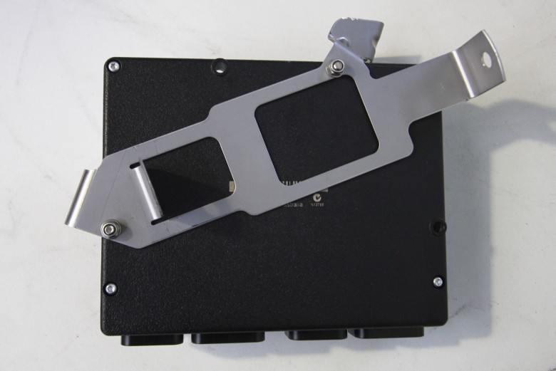
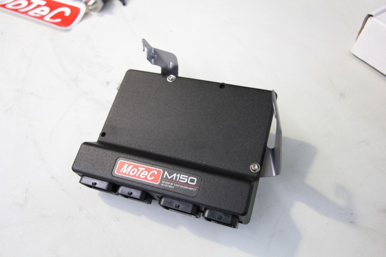
The M1 ECU which isn’t provided with any easy means of mounting. We removed the factory ECU bracket and managed to bolt the M150 on in place of the stock ECU. This tucks the ECU out of the way and keeps the interior tidy.
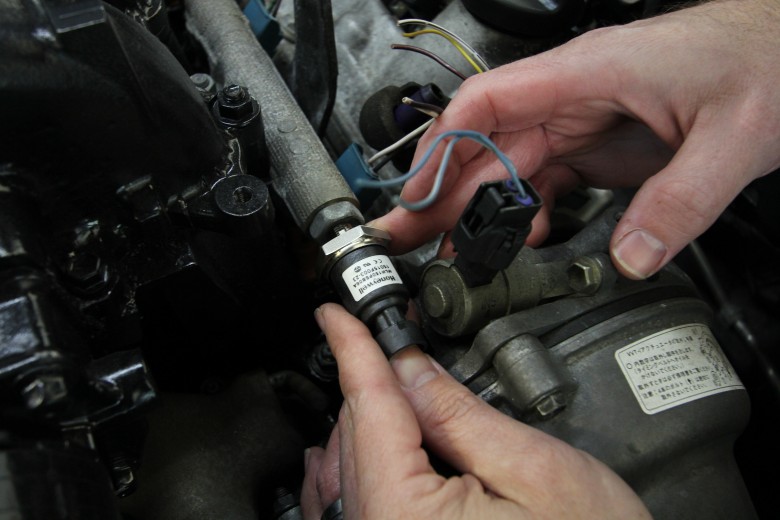
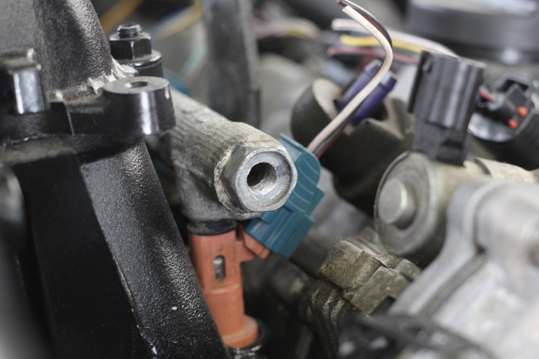
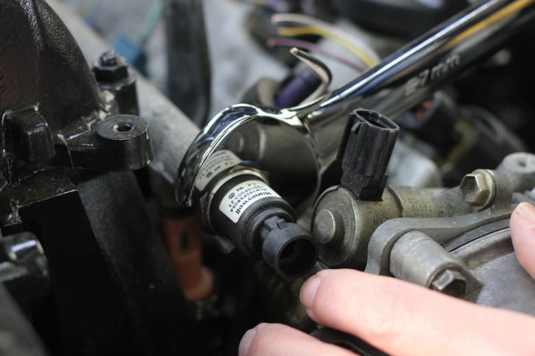
Ideally with the fuel pressure sensor, you want to be monitoring fuel pressure at the fuel rail which is the pressure that the injectors will see. In some situations room in the engine bay will dictate where we can physically mount the sensor, but in our case a neat solution was to drill and tap the blanking cap for the passengers side fuel rail.
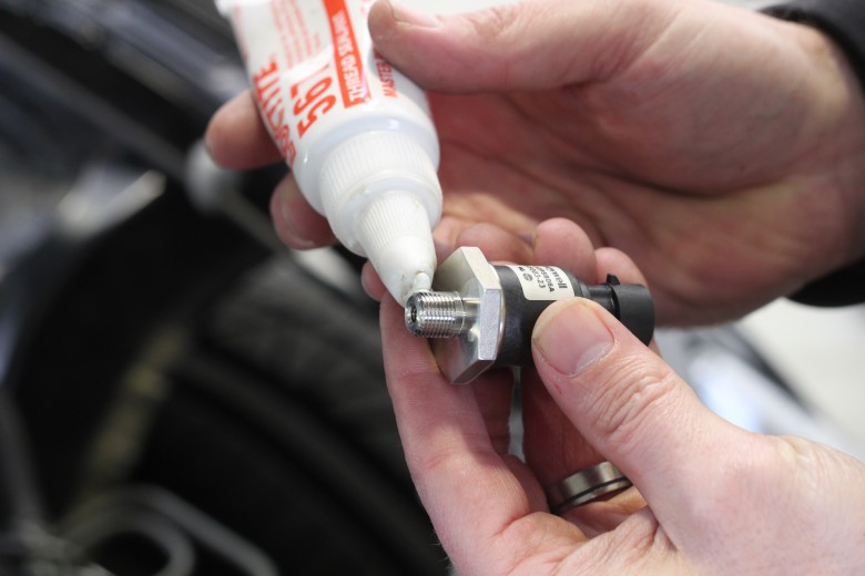
We sealed the pressure sensor with a teflon thread paste and fitted a new aluminium sealing washer before putting everything back together. With the fuel pressure sensor fitted, the MoTeC ECU can make fuelling adjustments based on actual fuel pressure and this helps improve the accuracy of the tune.
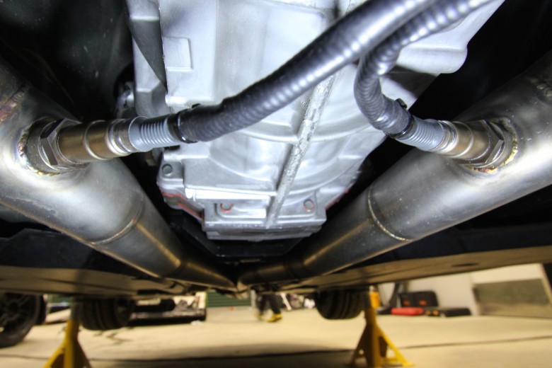
We also needed to mount the lambda sensors into the exhaust system so that we could measure the air fuel ratio. The hard work was already done here as the exhaust system already had fittings welded into each bank. It’s important when mounting these sensors to make sure that they are mounted horizontally or above. If the sensor is mounted to the underside of the exhaust it can be damaged by moisture, reducing sensor life.
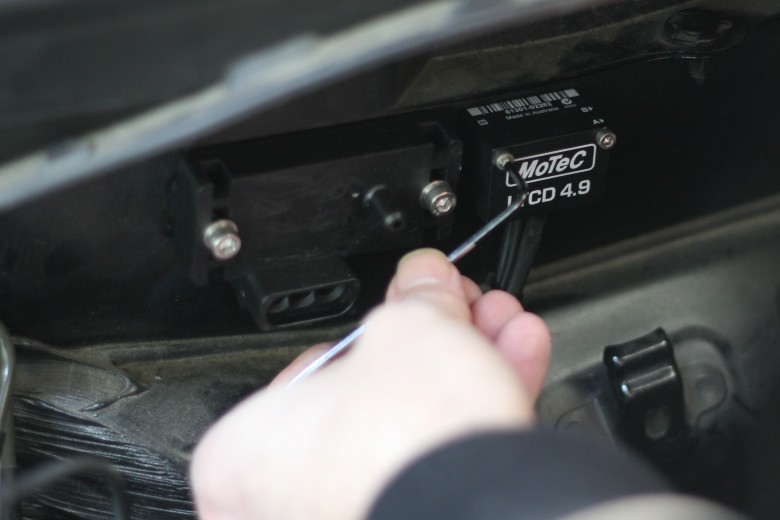
We mounted the MoTeC LTC unit and MAP sensor to the firewall behind the battery. This is to keep them both close to the engine but protect them from excessive heat. To mount these components we used Rivnuts which are a tidy way of adding a threaded hole into panel steel, providing a neat and professional result.
Before we pick up a set of wire strippers or a crimping tool though we need a complete plan of how we will approach the wiring and which wire will go to which terminal. This is a time consuming process but the time spent here will pay dividends later and ensure that we don’t make any mistakes and we will have documentation to refer back to later if we need to fault find anything. The problem with using DR25 as a protective sheath is that there is no way of adding any wires later on if we make a mistake. This makes proper planning even more essential.
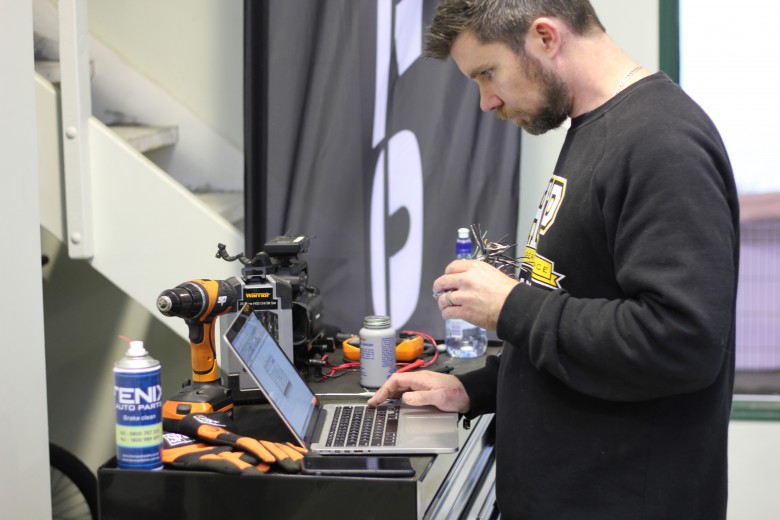
There are a few options when it comes to designing the engine harness depending what resources you have access to. If you have a factory workshop manual then often this will include pin out information for the ECU and bulkhead connectors. If you’re dealing with a car that’s sold in multiple countries often there are subtle differences between wire colours and pin locations that can trip you up. In our case we chose the slightly more labour intensive method of back probing the harness with a meter to confirm pin locations.
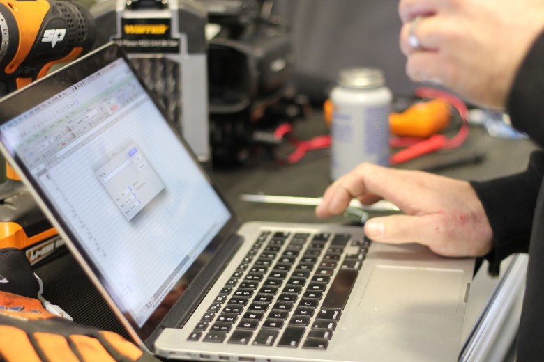
This data was then transferred to a spreadsheet where we could detail the pin location, function, and the corresponding pin location on the MoTeC ECU.

Once we had completed this spreadsheet we could compare the original functions with what we needed to run our 1UZFE V8 engine. Reallocating functions sometimes does mean that pins need to be swapped at the ECU connector too, as for example an ignition output to control a coil needs to be connected to one of the ignition drives in the ECU. With all the required inputs and outputs assigned, we even had enough spare inputs to wire our fuel pressure and oil pressure sensors through the bulkhead connector. This keeps the installation neat as there is only one harness to disconnect if the engine needs to come out.
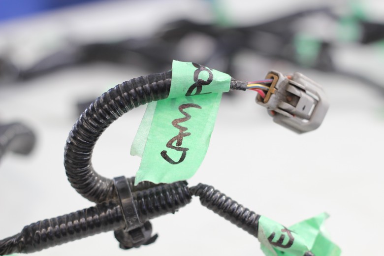
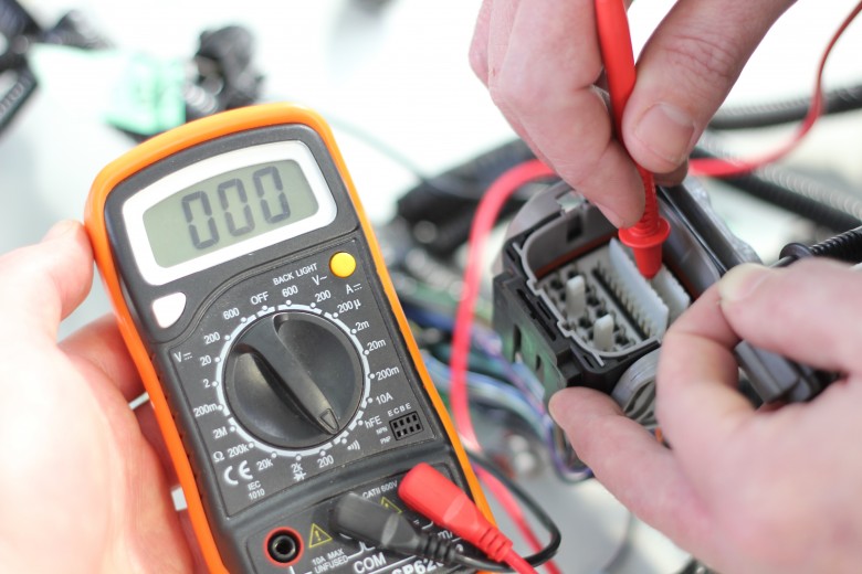
To make our job easier and to avoid confusion while back probing, we labeled all the plugs on the factory FA20 Harness.
Fitting a multimeter probe into some factory connectors can be difficult so here’s a pro tip - Instead of trying to fit the multimeter probe, insert a DTM terminal into the connector instead. Now you can connect your multimeter to this, ensuring a good connection.
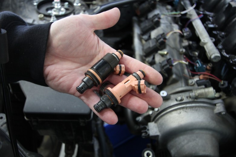
The MoTeC M1 has to have the correct data for the injectors fitted to the engine. For the M1’s volumetric efficiency fuel model to work accurately, it’s essential that the ECU knows what mass of fuel is delivered for a certain injector pulsewidth. To get this data we sent a couple of injectors to MoTeC in Melbourne where they could run them on their test bench to generate the right data for us. This isn’t something you want to leave till the last minute.
In the next instalment you’ll be able to follow through as we create the new wiring harness, we will show you a couple of wiring techniques we use, detail the materials we have chosen for the job and take you one step closer to being able to fire up the engine for the first time.


Comments
Using the original bulk head connectors is a brilliant idea which I'm using on my project, thanks for that!!
- Mtadros Australia
6 years ago
No one has commented on this page yet.